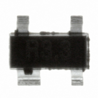
SR3.3.TCT Semtech, SR3.3.TCT Datasheet - Page 5

SR3.3.TCT
Manufacturer Part Number
SR3.3.TCT
Description
IC TVS ARRAY 2-LINE 3.3V SOT-143
Manufacturer
Semtech
Series
RailClamp®r
Datasheet
1.SR3.3.TCT.pdf
(7 pages)
Specifications of SR3.3.TCT
Voltage - Reverse Standoff (typ)
3.3V
Voltage - Breakdown
3.5V
Power (watts)
150W
Polarization
2 Channel Array - Unidirectional
Mounting Type
Surface Mount
Package / Case
SOT-143, SOT-143B, TO-253AA
Lead Free Status / RoHS Status
Lead free / RoHS Compliant
Other names
SR3.3TR
Available stocks
Company
Part Number
Manufacturer
Quantity
Price
Company:
Part Number:
SR3.3.TCT
Manufacturer:
Semtech
Quantity:
3 000
Part Number:
SR3.3.TCT
Manufacturer:
SEMTECH/美国升特
Quantity:
20 000
Board Layout Considerations for ESD Protection
Board Layout Considerations for ESD Protection
Board Layout Considerations for ESD Protection
Board Layout Considerations for ESD Protection
Board Layout Considerations for ESD Protection
Board layout plays an important role in the suppression
of extremely fast rise-time ESD transients. Recall that
the voltage developed across an inductive load is
proportional to the time rate of change of current
PIN Descriptions
through the load (V = L di/dt). The total clamping
voltage seen by the protected load will be the sum of
the TVS clamping voltage and the voltage due to the
parasitic inductance (V
inductance in the protection path can result in signifi-
cant voltage overshoot, reducing the effectiveness of
the suppression circuit. An ESD induced transient for
example reaches a peak in approximately 1ns. For a
30A pulse (per IEC 61000-4-2 Level 4), 1nH of series
inductance will increase the effective clamping voltage
by 30V
(V = 1x10
the following board layout guidelines are recom-
mended:
Matte Tin Lead Finish
Matte tin has become the industry standard lead-free
replacement for SnPb lead finishes. A matte tin finish
is composed of 100% tin solder with large grains.
Since the solder volume on the leads is small com-
pared to the solder paste volume that is placed on the
land pattern of the PCB, the reflow profile will be
determined by the requirements of the solder paste.
Therefore, these devices are compatible with both
lead-free and SnPb assembly techniques. In addition,
unlike other lead-free compositions, matte tin does not
have any added alloys that can cause degradation of
the solder joint.
PROTECTION PRODUCTS
Applications Information (continued)
2008 Semtech Corp.
Minimize the path length between the SR3.3 and
the protected line.
Place the SR3.3 near the RJ45 connector to
restrict transient coupling in nearby traces.
Minimize the path length (inductance) between the
RJ45 connector and the SR3.3.
-9
(30/1x10
-9
C(TOT)
)). For maximum effectiveness,
= V
C
+ L di/dt) . Parasitic
5
www.semtech.com
SR3.3


