SM8S24AHE3/2D Vishay, SM8S24AHE3/2D Datasheet - Page 3
SM8S24AHE3/2D
Manufacturer Part Number
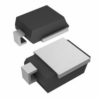
SM8S24AHE3/2D
Description
TVS 8W 24V 5% DO-218AB
Manufacturer
Vishay
Specifications of SM8S24AHE3/2D
Voltage - Reverse Standoff (typ)
24V
Voltage - Breakdown
26.7V
Power (watts)
8W
Polarization
Unidirectional
Mounting Type
Surface Mount
Package / Case
DO-218AB
Polarity
Unidirectional
Clamping Voltage
38.9 V
Operating Voltage
24 V
Breakdown Voltage
26.7 V
Peak Surge Current
170 A
Peak Pulse Power Dissipation
6600 W
Maximum Operating Temperature
+ 175 C
Minimum Operating Temperature
- 55 C
Dimensions
8.7(Max) mm W x 13.7(Max) mm L
Reverse Stand-off Voltage Vrwm
24V
Breakdown Voltage Range
26.7V To 29.5V
Clamping Voltage Vc Max
38.9V
Diode Configuration
Unidirectional
Peak Pulse Current Ippm
170A
Diode Case Style
DO-218AB
No. Of Pins
2
Rohs Compliant
Yes
Power Dissipation Pd
8W
Lead Free Status / RoHS Status
Lead free / RoHS Compliant
Available stocks
Company
Part Number
Manufacturer
Quantity
Price


Some vehicle manufactures apply different conditions for
the load dump test based on ISO-7637-2 pulse 5. The peak
clamped current of the load dump TVS will be estimated by
the following equation:
Calculation for peak clamping current
I
V
V
R
Figure 6a shows the current and voltage waveforms of
Vishay’s SM5S24A in the ISO 7637-2 test of 87 V V
V
Figure 6b shows the clamped voltage and current of load
dummp TVF fail in the ISO 7637-2 test of 87 V V
V
voltage drops to near zero, and the current passed through
the device is increased to the maximum allowed by the line
impedance.
Document Number: 88490
Revision: 09-Aug-10
I
PP
PP
in
c
batt.
batt.
i
: Line impedance
: Clamping voltage
: Peak clamping current
: Input voltage
=
, 0.75 Ω R
, 0.5 Ω R
Fig. 6a - Clamped Voltage and Current of SM5A24A
(
V
in
–
V
c
i
) R
i
and 400 ms pulse width.
⁄
and 400 ms pulse width. The clamping
i
Fig. 6 - For ISO-7637-2 Test Conditions, the Standard Condition is a V
in ISO 7637-2 Test
Transient Voltage Suppressors (TVS) for
DiodesAmericas@vishay.com, DiodesAsia@vishay.com,
V
V
S
For technical questions within your region, please contact one of the following:
r
V
(V)
Automotive Electronic Protection
P
100
50
0
0
and R
i
(Line Impedance) Range of 0.5 Ω to 4 Ω
S
S
, 13.5 V
, 13.5 V
100
JASO A-1
36.8 % of V
Line Impedance and Pulse Duration
JASO A-1:
ISO-7637:
P
200
Maximum clamping capability of Vishay load dump TVS of
ISO 7637-2 pulse 5 test condition with 13.5 V V
400 ms pulse width is as Figure 6c.
Fig. 6c - Maximum Clamping Capability of Vishay Load Dump TVS
Fig. 6b - Clamped Voltage and Current of Load Dump TVS
0.8 Ω, 200 ms
0.5 Ω min. (0.5 Ω to 4 Ω),
400 ms max. (40 ms to 400 ms)
DiodesEurope@vishay.com
Vishay General Semiconductor
300
ISO 7637
V
r
+ 10 % of V
S
Failures in ISO7637-2 Test
Range of 65 V to 87 V,
(ms)
in ISO7637-2 Test
S
400
Application Note
www.vishay.com
batt.
and
3
Related parts for SM8S24AHE3/2D
Image
Part Number
Description
Manufacturer
Datasheet
Request
R

Part Number:
Description:
Manufacturer:
Vishay Semiconductors
Datasheet:

Part Number:
Description:
TVS 8W 24V 5% DO-218AB
Manufacturer:
Vishay
Datasheet:
Part Number:
Description:
TVS Diodes - Transient Voltage Suppressors 8.0W 24V 5% Unidir
Manufacturer:
Vishay Semiconductors
Datasheet:
Part Number:
Description:
TVS Diodes - Transient Voltage Suppressors 8W 24V Unidirect
Manufacturer:
Vishay Semiconductors
Datasheet:
Part Number:
Description:
TVS Diodes - Transient Voltage Suppressors 8W 24V Unidirect
Manufacturer:
Vishay Semiconductors
Datasheet:

Part Number:
Description:
357-036-542-201 CARDEDGE 36POS DL .156 BLK LOPRO
Manufacturer:
Vishay
Datasheet:
Part Number:
Description:
357-036-542-201 CARDEDGE 36POS DL .156 BLK LOPRO
Manufacturer:
Vishay
Datasheet:
Part Number:
Description:
357-036-542-201 CARDEDGE 36POS DL .156 BLK LOPRO
Manufacturer:
Vishay
Datasheet:
Part Number:
Description:
357-036-542-201 CARDEDGE 36POS DL .156 BLK LOPRO
Manufacturer:
Vishay
Datasheet:
Part Number:
Description:
357-036-542-201 CARDEDGE 36POS DL .156 BLK LOPRO
Manufacturer:
Vishay
Datasheet:
Part Number:
Description:
357-036-542-201 CARDEDGE 36POS DL .156 BLK LOPRO
Manufacturer:
Vishay
Datasheet:
Part Number:
Description:
357-036-542-201 CARDEDGE 36POS DL .156 BLK LOPRO
Manufacturer:
Vishay
Datasheet:
Part Number:
Description:
357-036-542-201 CARDEDGE 36POS DL .156 BLK LOPRO
Manufacturer:
Vishay
Datasheet:
Part Number:
Description:
357-036-542-201 CARDEDGE 36POS DL .156 BLK LOPRO
Manufacturer:
Vishay
Datasheet: