SMF24CT1G ON Semiconductor, SMF24CT1G Datasheet - Page 2
SMF24CT1G
Manufacturer Part Number
SMF24CT1G
Description
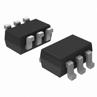
IC TVS ARRAY 5LINE 100W SOT-363
Manufacturer
ON Semiconductor
Datasheet
1.SMF05CT1G.pdf
(6 pages)
Specifications of SMF24CT1G
Voltage - Reverse Standoff (typ)
24V
Voltage - Breakdown
26.7V
Power (watts)
100W
Polarization
5 Channel Array - Bidirectional
Mounting Type
Surface Mount
Package / Case
SC-70-6, SC-88, SOT-363
Lead Free Status / RoHS Status
Lead free / RoHS Compliant
Other names
SMF24CT1G
SMF24CT1GOSTR
SMF24CT1GOSTR
Available stocks
Company
Part Number
Manufacturer
Quantity
Price
Company:

Part Number:
SMF24CT1G
Manufacturer:
ON Semiconductor
Quantity:
1 400
Company:
Part Number:
SMF24CT1G
Manufacturer:
ON
Quantity:
30 000
Company:
Part Number:
SMF24CT1G
Manufacturer:
ON
Quantity:
30 000
Part Number:
SMF24CT1G
Manufacturer:
ON/安森美
Quantity:
20 000


SMF05C ELECTRICAL CHARACTERISTICS
SMF12C ELECTRICAL CHARACTERISTICS
SMF15C ELECTRICAL CHARACTERISTICS
SMF24C ELECTRICAL CHARACTERISTICS
2. TVS devices are normally selected according to the working peak reverse voltage (V
3. V
Reverse Working Voltage
Breakdown Voltage
Reverse Leakage Current
Clamping Voltage
Clamping Voltage
Maximum Peak Pulse Current
Capacitance
Reverse Working Voltage
Breakdown Voltage
Reverse Leakage Current
Clamping Voltage
Clamping Voltage
Maximum Peak Pulse Current
Capacitance
Reverse Working Voltage
Breakdown Voltage
Reverse Leakage Current
Clamping Voltage
Clamping Voltage
Maximum Peak Pulse Current
Capacitance
Reverse Working Voltage
Breakdown Voltage
Reverse Leakage Current
Clamping Voltage
Clamping Voltage
Maximum Peak Pulse Current
Capacitance
or continuous peak operating voltage level.
BR
is measured at pulse test current I
Parameter
Parameter
Parameter
Parameter
T
Symbol
Symbol
Symbol
Symbol
.
V
V
V
V
V
V
V
V
RWM
I
RWM
I
RWM
I
RWM
I
V
V
V
V
V
V
V
V
C
C
C
C
I
I
I
I
PP
PP
PP
PP
BR
BR
BR
BR
R
R
R
R
C
C
C
C
C
C
C
C
J
J
J
J
(T
(T
(T
(T
J
J
J
J
(Note 2)
I
V
I
I
8 x 20 ms Waveform
V
(Note 2)
I
V
I
I
8 x 20 ms Waveform
V
(Note 2)
I
V
I
I
8 x 20 ms Waveform
V
(Note 2)
I
V
I
I
8 x 20 ms Waveform
V
T
PP
PP
T
PP
PP
T
PP
PP
T
PP
PP
= 25°C unless otherwise specified)
= 25°C unless otherwise specified)
= 25°C, unless otherwise specified)
= 25°C, unless otherwise specified)
RWM
R
RWM
R
RWM
R
RWM
R
http://onsemi.com
= 1 mA, (Note 3)
= 1 mA, (Note 3)
= 1 mA, (Note 3)
= 1 mA, (Note 3)
= 0 V, f = 1 MHz (Line to GND)
= 0 V, f = 1 MHz (Line to GND)
= 0 V, f = 1 MHz (Line to GND)
= 0 V, f = 1 MHz (Line to GND)
= 5 A (8 x 20 ms Waveform)
= 8 A (8 x 20 ms Waveform)
= 3 A (8 x 20 ms Waveform)
= 6 A (8 x 20 ms Waveform)
= 1 A (8 x 20 ms Waveform)
= 5 A (8 x 20 ms Waveform)
= 1 A (8 x 20 ms Waveform)
= 2.5 A (8 x 20 ms Waveform)
= 5 V
= 12 V
= 15 V
= 24 V
2
Conditions
Conditions
Conditions
Conditions
RWM
), which should be equal or greater than the DC
13.3
26.7
Min
Min
Min
Min
6.2
17
0.07
0.01
0.01
0.01
Typ
Typ
Typ
Typ
80
40
33
21
Max
12.5
Max
Max
Max
130
5.0
7.2
5.0
9.8
8.0
0.1
6.0
1.0
5.0
1.0
2.5
12
15
21
23
60
15
19
23
29
45
24
32
40
44
25
Unit
Unit
Unit
Unit
mA
pF
mA
pF
mA
pF
mA
pF
V
V
V
V
A
V
V
V
V
A
V
V
V
V
A
V
V
V
V
A
Related parts for SMF24CT1G
Image
Part Number
Description
Manufacturer
Datasheet
Request
R

Part Number:
Description:
(SMFxxC) 5-Line Transient Voltage Suppressor Array
Manufacturer:
ON Semiconductor

Part Number:
Description:
IC TVS ARRAY 5-BI 5V SC70-6
Manufacturer:
Semtech
Datasheet:
Part Number:
Description:
ON Semiconductor [VOLTAGE REGULATOR]
Manufacturer:
ON Semiconductor
Datasheet:
Part Number:
Description:
357-036-542-201 CARDEDGE 36POS DL .156 BLK LOPRO
Manufacturer:
ON Semiconductor
Datasheet:
Part Number:
Description:
357-036-542-201 CARDEDGE 36POS DL .156 BLK LOPRO
Manufacturer:
ON Semiconductor
Datasheet:
Part Number:
Description:
357-036-542-201 CARDEDGE 36POS DL .156 BLK LOPRO
Manufacturer:
ON Semiconductor
Datasheet:
Part Number:
Description:
357-036-542-201 CARDEDGE 36POS DL .156 BLK LOPRO
Manufacturer:
ON Semiconductor
Datasheet:
Part Number:
Description:
357-036-542-201 CARDEDGE 36POS DL .156 BLK LOPRO
Manufacturer:
ON Semiconductor
Datasheet:
Part Number:
Description:
357-036-542-201 CARDEDGE 36POS DL .156 BLK LOPRO
Manufacturer:
ON Semiconductor
Datasheet:
Part Number:
Description:
357-036-542-201 CARDEDGE 36POS DL .156 BLK LOPRO
Manufacturer:
ON Semiconductor
Datasheet:
Part Number:
Description:
357-036-542-201 CARDEDGE 36POS DL .156 BLK LOPRO
Manufacturer:
ON Semiconductor
Datasheet:
Part Number:
Description:
357-036-542-201 CARDEDGE 36POS DL .156 BLK LOPRO
Manufacturer:
ON Semiconductor
Datasheet:
Part Number:
Description:
357-036-542-201 CARDEDGE 36POS DL .156 BLK LOPRO
Manufacturer:
ON Semiconductor
Datasheet:
Part Number:
Description:
Manufacturer:
ON Semiconductor
Datasheet: