NUP2201MR6T1 ON Semiconductor, NUP2201MR6T1 Datasheet - Page 5
NUP2201MR6T1
Manufacturer Part Number
NUP2201MR6T1
Description
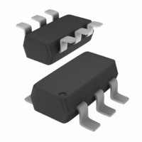
IC TVS DIODE ARRAY HS LINE 6TSOP
Manufacturer
ON Semiconductor
Datasheet
1.NUP2201MR6T1.pdf
(8 pages)
Specifications of NUP2201MR6T1
Voltage - Reverse Standoff (typ)
5V
Voltage - Breakdown
6V
Power (watts)
500W
Polarization
2 Channel Array - Unidirectional
Mounting Type
Surface Mount
Package / Case
SC-74-6
Lead Free Status / RoHS Status
Contains lead / RoHS non-compliant
Other names
NUP2201MR6T1OS
NUP2201MR6T1OS
NUP2201MR6T1OSTR
NUP2201MR6T1OS
NUP2201MR6T1OSTR
Available stocks
Company
Part Number
Manufacturer
Quantity
Price
Company:

Part Number:
NUP2201MR6T1G
Manufacturer:
ON Semiconductor
Quantity:
32 941
Company:
Part Number:
NUP2201MR6T1G
Manufacturer:
ON
Quantity:
30 000
Part Number:
NUP2201MR6T1G
Manufacturer:
ON/安森美
Quantity:
20 000


designed to protect sensitive electronics such as
communications systems, computers, and computer
peripherals against damage due to ESD events or transient
overvoltage conditions. Because of its low capacitance, it
can be used on high speed I/O data lines. The integrated
design of the NUP2201MR6 offers surge rated, low
capacitance steering diodes and a TVS diode integrated in
a single package (TSOP−6). If a transient condition occurs,
the steering diodes will drive the transient to the positive rail
of the power supply or to ground. The TVS device protects
the power line against overvoltage conditions to avoid
damage to the power supply and any downstream
components.
NUP2201MR6 Configuration Options
against transient overvoltage conditions by driving them to
a fixed reference point for clamping purposes. The steering
diodes will be forward biased whenever the voltage on the
protected line exceeds the reference voltage (Vf or V
Vf). The diodes will force the transient current to bypass the
sensitive circuit.
reference is connected at pin 2. This pin must be connected
directly to ground by using a ground plane to minimize the
PCB’s ground inductance. It is very important to reduce the
PCB trace lengths as much as possible to minimize parasitic
inductance.
Option 1
V
positive supply rail (V
the supply voltage. The internal TVS diode prevents
overvoltage on the supply rail. Biasing of the steering diodes
reduces their capacitance.
CC
The NUP2201MR6 is a low capacitance TVS diode array
The NUP2201MR6 is able to protect two data lines
Data lines are connected at pins 1 and 6. The negative
Protection of two data lines and the power supply using
For this configuration, connect pin 5 directly to the
I/O 1
I/O 2
as reference.
1
2
3
CC
), the data lines are referenced to
6
5
4
APPLICATIONS INFORMATION
V
CC
http://onsemi.com
CC
+
5
Option 2
isolation resistor.
by connecting a series resistor between pin 5 and V
10 kW resistor is recommended for this application. This
will maintain bias on the internal TVS and steering diodes,
reducing their capacitance.
Option 3
as reference.
those cases in which a fully isolated power supply is
required, the internal TVS can be used as the reference. For
these applications, pin 5 is not connected. In this
configuration, the steering diodes will conduct whenever the
voltage on the protected line exceeds the working voltage of
the TVS plus one diode drop (Vc = Vf + V
ESD Protection of Power Supply Lines
a supply rail provides advantages. Biasing the diodes
reduces their capacitance and minimizes signal distortion.
Implementing this topology with discrete devices does have
disadvantages. This configuration is shown below:
Protection of two data lines with bias and power supply
The NUP2201MR6 can be isolated from the power supply
Protection of two data lines using the internal TVS diode
In applications lacking a positive supply reference or
When using diodes for data line protection, referencing to
I/O 1
I/O 2
I/O 1
I/O 2
1
2
3
1
2
3
6
5
4
6
5
4
TVS
).
V
NC
CC
10 k
CC
. A
Related parts for NUP2201MR6T1
Image
Part Number
Description
Manufacturer
Datasheet
Request
R

Part Number:
Description:
Low Capacitance Tsop-6 Diode-tvs Array For High Speed Data Lines Protection
Manufacturer:
ON Semiconductor
Datasheet:
Part Number:
Description:
ON Semiconductor [VOLTAGE REGULATOR]
Manufacturer:
ON Semiconductor
Datasheet:
Part Number:
Description:
357-036-542-201 CARDEDGE 36POS DL .156 BLK LOPRO
Manufacturer:
ON Semiconductor
Datasheet:
Part Number:
Description:
357-036-542-201 CARDEDGE 36POS DL .156 BLK LOPRO
Manufacturer:
ON Semiconductor
Datasheet:
Part Number:
Description:
357-036-542-201 CARDEDGE 36POS DL .156 BLK LOPRO
Manufacturer:
ON Semiconductor
Datasheet:
Part Number:
Description:
357-036-542-201 CARDEDGE 36POS DL .156 BLK LOPRO
Manufacturer:
ON Semiconductor
Datasheet:
Part Number:
Description:
357-036-542-201 CARDEDGE 36POS DL .156 BLK LOPRO
Manufacturer:
ON Semiconductor
Datasheet:
Part Number:
Description:
357-036-542-201 CARDEDGE 36POS DL .156 BLK LOPRO
Manufacturer:
ON Semiconductor
Datasheet:
Part Number:
Description:
357-036-542-201 CARDEDGE 36POS DL .156 BLK LOPRO
Manufacturer:
ON Semiconductor
Datasheet:
Part Number:
Description:
357-036-542-201 CARDEDGE 36POS DL .156 BLK LOPRO
Manufacturer:
ON Semiconductor
Datasheet:
Part Number:
Description:
357-036-542-201 CARDEDGE 36POS DL .156 BLK LOPRO
Manufacturer:
ON Semiconductor
Datasheet:
Part Number:
Description:
357-036-542-201 CARDEDGE 36POS DL .156 BLK LOPRO
Manufacturer:
ON Semiconductor
Datasheet:
Part Number:
Description:
Manufacturer:
ON Semiconductor
Datasheet:
Part Number:
Description:
Manufacturer:
ON Semiconductor
Datasheet: