1N6276ARL4 ON Semiconductor, 1N6276ARL4 Datasheet
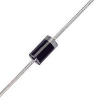
TVS 1500W 16V UNIDIRECT AXIAL

1N6276ARL4

Manufacturer Part Number
1N6276ARL4
Description
TVS 1500W 16V UNIDIRECT AXIAL
Manufacturer
ON Semiconductor
Series
Mosorb™r
Datasheet

Specifications of 1N6276ARL4

Voltage - Reverse Standoff (typ)
13.6V
Voltage - Breakdown
15.2V
Power (watts)
1500W
Polarization
Unidirectional
Mounting Type
Through Hole
Package / Case
Axial
Polarity
Unidirectional
Clamping Voltage
22.5 V
Operating Voltage
13.6 V
Breakdown Voltage
15.2 V
Peak Surge Current
67 A
Peak Pulse Power Dissipation
1500 W
Maximum Operating Temperature
+ 150 C
Minimum Operating Temperature
- 65 C
Dimensions
5.3 (Max) mm W x 9.5 (Max) mm L
Lead Free Status / RoHS Status
Contains lead / RoHS non-compliant

Available stocks

Company
Part Number
Manufacturer
Quantity
Price
Part Number:
1N6276ARL4G
Manufacturer:
ON/安森美
Quantity:
20 000
1N6267A Series
1500 Watt Mosorbt Zener
Transient Voltage
Suppressors
Unidirectional*
components from high voltage, high−energy transients. They have
excellent clamping capability, high surge capability, low zener
i m p e d a n c e a n d f a s t r e s p o n s e t i m e . T h e s e d e v i c e s a r e
ON Semiconductor’s exclusive, cost-effective, highly reliable
Surmetict axial leaded package and are ideally-suited for use in
communication systems, numerical controls, process controls,
medical equipment, business machines, power supplies and many
other industrial/consumer applications, to protect CMOS, MOS and
Bipolar integrated circuits.
Features
Mechanical Characteristics
CASE:
FINISH:
readily solderable
MAXIMUM LEAD TEMPERATURE FOR SOLDERING PURPOSES:
230 C, 1/16 in from the case for 10 seconds
POLARITY:
MOUNTING POSITION:
*For additional information on our Pb−Free strategy and soldering details, please
December, 2004 − Rev. 6
download the ON Semiconductor Soldering and Mounting Techniques
Reference Manual, SOLDERRM/D.
Mosorb devices are designed to protect voltage sensitive
finish only*
Working Peak Reverse Voltage Range − 5.8 V to 214 V
Peak Power − 1500 Watts @ 1 ms
ESD Rating of Class 3 (>16 kV) per Human Body Model
Maximum Clamp Voltage @ Peak Pulse Current
Low Leakage < 5 mA Above 10 V
UL 497B for Isolated Loop Circuit Protection
Response Time is Typically < 1 ns
These devices are manufactured with a Pb−Free external lead
Semiconductor Components Industries, LLC, 2004
Void-free, transfer-molded, thermosetting plastic
All external surfaces are corrosion resistant and leads are
Cathode indicated by polarity band
Any
1
†For information on tape and reel specifications,
*1N6302A Not Available in 1500/Tape & Reel
Preferred devices are recommended choices for future use
and best overall value.
1.5KExxxA
1.5KExxxARL4
1N6xxxA
1N6xxxARL4*
including part orientation and tape sizes, please
refer to our Tape and Reel Packaging Specifications
Brochure, BRD8011/D.
Device
Cathode
L
1N6xxxA
1.5KExxxA
YY
WW
ORDERING INFORMATION
MARKING DIAGRAM
http://onsemi.com
AXIAL LEAD
Axial Lead
Axial Lead
Axial Lead
Axial Lead
Package
CASE 41A
PLASTIC
= Assembly Location
= JEDEC Device Code
= ON Device Code
= Year
= Work Week
L
1N6
xxxA
1.5KE
xxxA
YYWW
Publication Order Number:
1500/Tape & Reel
1500/Tape & Reel
500 Units/Box
500 Units/Box
Anode
Shipping
1N6267A/D

Related parts for 1N6276ARL4

1N6276ARL4 Summary of contents

Page 1

... C, 1/16 in from the case for 10 seconds Cathode indicated by polarity band POLARITY: MOUNTING POSITION: Any *For additional information on our Pb−Free strategy and soldering details, please download the ON Semiconductor Soldering and Mounting Techniques Reference Manual, SOLDERRM/D. Semiconductor Components Industries, LLC, 2004 December, 2004 − Rev. 6 http://onsemi.com Cathode ...

Page 2

MAXIMUM RATINGS Rating Peak Power Dissipation (Note Steady State Power Dissipation @ Lead Length = 3 Derated above Thermal Resistance, Junction−to−Lead Forward Surge Current ...

Page 3

... Devices listed in bold, italic are ON Semiconductor Preferred devices. Preferred devices are recommended choices for future use and best overall value. 3. 1/2 sine wave (or equivalent square wave 8.3 ms, duty cycle = 4 pulses per minute maximum. 4. Indicates JEDEC registered data 5. A transient suppressor is normally selected according to the maximum working peak reverse voltage (V greater than the dc or continuous peak operating voltage level ...

Page 4

PULSE WIDTH P Figure 1. Pulse Rating Curve 1N6373, ICTE-5, MPTE-5, through 1N6389, ICTE-45, C, MPTE-45, C 10,000 1000 MEASURED @ V RWM 100 ...

Page 5

ICTE-5, MPTE-5, through 1N6389, ICTE-45, C, MPTE-45, C 1000 500 = 200 100 0.3 0.5 0 INSTANTANEOUS INCREASE ...

Page 6

... Strike Voltage Breakdown test, Endurance 1. Clipper-bidirectional devices are available in the 1.5KEXXA series and are designated with a “CA” suffix; for example, 1.5KE18CA. Contact your nearest ON Semiconductor representative. 2. Clipper-bidirectional part numbers are tested in both directions to electrical parameters in preceding table (except for V which does not apply) ...

Page 7

Series OUTLINE DIMENSIONS MOSORB CASE 41A−04 ISSUE http://onsemi.com 7 NOTES: 1. DIMENSIONING AND TOLERANCING PER ANSI Y14.5M, 1982. 2. CONTROLLING DIMENSION: INCH. 3. LEAD FINISH AND DIAMETER UNCONTROLLED IN DIMENSION P. ...

Page 8

... Fax: 480−829−7709 or 800−344−3867 Toll Free USA/Canada Email: orderlit@onsemi.com 1N6267A Series N. American Technical Support: 800−282−9855 Toll Free USA/Canada Japan: ON Semiconductor, Japan Customer Focus Center 2−9−1 Kamimeguro, Meguro−ku, Tokyo, Japan 153−0051 Phone: 81−3−5773−3850 http://onsemi.com 8 ON Semiconductor Website: http://onsemi ...

Related keywords