SMF6.0AT1 ON Semiconductor, SMF6.0AT1 Datasheet - Page 6
SMF6.0AT1
Manufacturer Part Number
SMF6.0AT1
Description
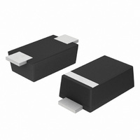
IC TVS ZENER 200W 6.0V SOD123FL
Manufacturer
ON Semiconductor
Datasheet
1.SMF78AT1.pdf
(8 pages)
Specifications of SMF6.0AT1
Voltage - Reverse Standoff (typ)
6V
Voltage - Breakdown
6.67V
Power (watts)
200W
Polarization
Unidirectional
Mounting Type
Surface Mount
Package / Case
SOD-123 Flat Leads
Lead Free Status / RoHS Status
Contains lead / RoHS non-compliant
Available stocks
Company
Part Number
Manufacturer
Quantity
Price
Company:

Part Number:
SMF6.0AT1G
Manufacturer:
DIODES
Quantity:
63 000
Company:
Part Number:
SMF6.0AT1G
Manufacturer:
ON
Quantity:
30 000


total design. The footprint for the semiconductor packages
must be the correct size to insure proper solder connection
function of the mounting pad size. This can vary from the
minimum pad size for soldering to a pad size given for
maximum power dissipation. Power dissipation for a
surface mount device is determined by T
maximum rated junction temperature of the die, R
thermal resistance from the device junction to ambient, and
the operating temperature, T
on the data sheet for the SOD−123 Flat Lead package, P
can be calculated as follows:
ratings table on the data sheet. Substituting these values
into the equation for an ambient temperature T
temperature of the device. When the entire device is heated
to a high temperature, failure to complete soldering within
a short time could result in device failure. Therefore, the
following items should always be observed in order to
minimize the thermal stress to which the devices are
subjected.
INFORMATION FOR USING THE SOD−123 FLAT LEAD SURFACE MOUNT PACKAGE
Surface mount board layout is a critical portion of the
The power dissipation of the SOD−123 Flat Lead is a
The values for the equation are found in the maximum
The melting temperature of solder is higher than the rated
Always preheat the device.
The delta temperature between the preheat and
soldering should be 100 C or less.*
When preheating and soldering, the temperature of the
leads and the case must not exceed the maximum
temperature ratings as shown on the data sheet. When
using infrared heating with the reflow soldering
method, the difference shall be a maximum of 10 C.
MINIMUM RECOMMENDED FOOTPRINT FOR SURFACE MOUNTED APPLICATIONS
P
D
=
T
J(max)
A
. Using the values provided
R
JA
RECOMMENDED FOOTPRINT FOR SOD−123FL
− T
A
POWERMITE POWER DISSIPATION
É É É
É É É
É É É
É É É
É É É
SOLDERING PRECAUTIONS
J(max)
A
SMF5.0AT1 Series
of 25 C,
http://onsemi.com
JA
, the
, the
D
0.093
0.165
2.36
4.19
6
interface between the board and the package. With the
correct pad geometry, the packages will self align when
subjected to a solder reflow process.
one can calculate the power dissipation of the device which
in this case is 385 milliwatts.
assumes the use of the recommended footprint on a glass
epoxy printed circuit board to achieve a power dissipation
of 385 milliwatts. There are other alternatives to achieving
higher power dissipation from the SOD−123 Flat Lead
package. Another alternative would be to use a ceramic
substrate or an aluminum core board such as Thermal
Clad . Using a board material such as Thermal Clad, an
aluminum core board, the power dissipation can be doubled
using the same footprint.
* Soldering a device without preheating can cause excessive
thermal shock and stress which can result in damage to the
device.
The 325 C/W for the SOD−123 Flat Lead package
The soldering temperature and time shall not exceed
260 C for more than 10 seconds.
When shifting from preheating to soldering, the
maximum temperature gradient shall be 5 C or less.
After soldering has been completed, the device should
be allowed to cool naturally for at least three minutes.
Gradual cooling should be used as the use of forced
cooling will increase the temperature gradient and
result in latent failure due to mechanical stress.
Mechanical stress or shock should not be applied
during cooling.
É É É
É É É
É É É
É É É
É É É
0.036
0.91
P
D
= 150 C − 25 C = 385 milliwatts
325 C/W
inches
mm
0.048
1.22
Related parts for SMF6.0AT1
Image
Part Number
Description
Manufacturer
Datasheet
Request
R

Part Number:
Description:
IC TVS ARRAY 5-BI 5V SC70-6
Manufacturer:
Semtech
Datasheet:

Part Number:
Description:
ON Semiconductor [VOLTAGE REGULATOR]
Manufacturer:
ON Semiconductor
Datasheet:
Part Number:
Description:
357-036-542-201 CARDEDGE 36POS DL .156 BLK LOPRO
Manufacturer:
ON Semiconductor
Datasheet:
Part Number:
Description:
357-036-542-201 CARDEDGE 36POS DL .156 BLK LOPRO
Manufacturer:
ON Semiconductor
Datasheet:
Part Number:
Description:
357-036-542-201 CARDEDGE 36POS DL .156 BLK LOPRO
Manufacturer:
ON Semiconductor
Datasheet:
Part Number:
Description:
357-036-542-201 CARDEDGE 36POS DL .156 BLK LOPRO
Manufacturer:
ON Semiconductor
Datasheet:
Part Number:
Description:
357-036-542-201 CARDEDGE 36POS DL .156 BLK LOPRO
Manufacturer:
ON Semiconductor
Datasheet:
Part Number:
Description:
357-036-542-201 CARDEDGE 36POS DL .156 BLK LOPRO
Manufacturer:
ON Semiconductor
Datasheet:
Part Number:
Description:
357-036-542-201 CARDEDGE 36POS DL .156 BLK LOPRO
Manufacturer:
ON Semiconductor
Datasheet:
Part Number:
Description:
357-036-542-201 CARDEDGE 36POS DL .156 BLK LOPRO
Manufacturer:
ON Semiconductor
Datasheet:
Part Number:
Description:
357-036-542-201 CARDEDGE 36POS DL .156 BLK LOPRO
Manufacturer:
ON Semiconductor
Datasheet:
Part Number:
Description:
357-036-542-201 CARDEDGE 36POS DL .156 BLK LOPRO
Manufacturer:
ON Semiconductor
Datasheet:
Part Number:
Description:
Manufacturer:
ON Semiconductor
Datasheet:
Part Number:
Description:
Manufacturer:
ON Semiconductor
Datasheet: