RZB108DHFR Sullins Connector Solutions, RZB108DHFR Datasheet - Page 61
RZB108DHFR
Manufacturer Part Number
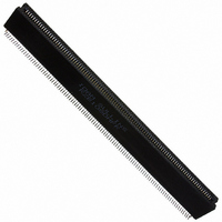
RZB108DHFR
Description
CONN EDGE DUAL .050 SMD 216 POS
Manufacturer
Sullins Connector Solutions
Datasheet
1.RZB13DHFR.pdf
(132 pages)
Specifications of RZB108DHFR
Card Type
Dual Edge
Card Thickness
0.062" (1.57mm)
Gender
Female
Number Of Positions
216
Pitch
0.050" (1.27mm)
Number Of Rows
2
Mounting Type
Surface Mount
Features
Board Lock
Contact Finish
Gold
Contact Finish Thickness
10µin (0.25µm)
Color
Black
Lead Free Status / RoHS Status
Contains lead / RoHS non-compliant
Other names
S3225


PART NUMBER CODING
DIMENSIONS
Tolerances with PPS Insulator Material may vary slightly due to shrinkage differential; Consult Factory.
POSITIONS/
CONTACTS
MATERIALS (Insulator/Contact)
CONTACT FINISH - RoHS Compliant
CONTACT CENTERS
All platings are Lead Free and have .000050” Nickel underplate
M =
NUMBER OF CONTACT POSITIONS
28/56
36/72
43/86
*F = PPS/Spinodal (Overall Gold Plating Only)
*C = PPS/Beryllium Nickel (Overall Gold Plating Only)
*W = PEEK/Beryllium Nickel (Overall Gold Plating Only)
B =
C =
G =
Y =
S =
E =
.025[0.64]
G = PA9T/Phosphor bronze
H = PBT/Beryllium Copper
A = PPS/Beryllium Copper
M = .156” [3.96mm]
E = PBT/Phosphor Bronze (Standard)
R = PPS/Phosphor Bronze
*Consult Factory for availability.
J = PA9T/Beryllium Copper
28 (14/14), 36 or 43
www.sullinscorp.com
.245[6.22]
Consult Factory for Special Soldering Guidelines
.431[10.95]
.000100” Pure Tin, Matte
A±.008
5.460
6.552
Contact Surface
Contact Surface
.000010” Gold
.000030” Gold
.000010” Gold
.000030” Gold
.000010” Gold
.000030” Gold
Dimensions in [ ] are in millimeters, all others are in inches.
B±.008
4.660
5.766
6.810
KEY THICK .046 [1.17]
1
A
.265 [6.73] INSERTION DEPTH
2
B C
REFER TO MOUNTING STYLE
3
|
C±.015
4.780
5.906
7.000
4
D E
760-744-0125
2.028[51.51]
5
.156 [3.96] TYP.
36 OR 43 POSITIONS (-S37 MODIFICATION)
F
6
INCHES
28 POSITIONS (-S92 MODIFICATION)
H
7
.000100” Pure Tin, Matte
.000100” Pure Tin, Matte
.000100” Pure Tin, Matte
8
J
D±.010
5.093
6.219
7.302
9 10 11 12 13 14 15
K
Overall Plating
L M
.000005” Gold
.000005” Gold
.000010” Gold
.000010” Gold
Termination
Special Body Configuration Dip Solder/Eyelet/Right Angle
N P
.156” [3.96mm] Contact Centers, .431” Insulator Height
E MAX
5.427
6.566
7.643
|
R S
toll-free 888-774-3100
C
B
A
D
E
B
D
E
C
E B M 43 D RT H - S37
REFER TO TERMINATION TYPE
16 17 18 19 20 21 22 23 24 25 26 27 28
T U
.280[7.11]
F±.005
0.438
0.438
0.500
V W X
.140 [3.56], 2 PLS.
2.028[51.51]
Y
Z A
A±0.20
138.68
166.42
_ _
B
C
_
D E
_ _ _
B±0.20
118.36
146.46
172.97
|
F
fax 760-744-6081
-S37 = Reverse Contact ID & Shorter Card Slot Length
-S92 = Center Barrier Molded in Card Slot
RA = .125” Right Angle Dip Solder
SA = Long Right Angle Dip Solder
RX = .200” x .137” Dip Solder
RU = .200” x .225” Dip Solder
SU = .210”[5.33mm] Centered Dip Solder
RT = .140” x .137” Dip Solder
RK = .140” x .225” Dip Solder
RY = .140” x .425” Dip Solder
RP = .200” x .408” Dip Solder
SX = .110”[2.79mm] Centered Dip Solder
SE = .007”[.18mm] Thick Eyelet
RE = .014”[.36mm] Thick Eyelet
D = Dual
D = Dual Row/ Crimp to Center for Single
H = Half Loaded
MOUNTING STYLE (Opposite Page)
TERMINATION TYPE (Opposite Page)
READOUT (Opposite Page)
H = .125”[3.18mm] Clearance Holes
N = No Mounting
I = Threaded Insert
S = Side Mounting
F = Floating Bobbin
C±0.38
121.41
150.01
177.80
[MILLIMETERS]
F
Readout (SX, SU Termination Only)
MODIFICATION CODE
F
D±0.25
129.36
157.96
185.47
CONTACT MARKINGS
(LETTERS G, I , O & Q NOT USED)
SIZE 28
1 2 3 ... 26 27 28
A B C ... D E F
SIZES 36 & 43
A B C ... R ... Y
1 2 3 ... 36 ... 43
|
info@sullinscorp.com
E MAX
137.85
166.78
194.13
Sullins Edgecards
F±0.13
11.13
11.13
12.70
(Consult Factory)
BARRIER
CENTER
YES
NO
NO
61
Related parts for RZB108DHFR
Image
Part Number
Description
Manufacturer
Datasheet
Request
R

Part Number:
Description:
CONN HEADER HM C UNSHIELD 55POS
Manufacturer:
Sullins Connector Solutions
Datasheet:

Part Number:
Description:
CONN HEADER HM B25 SHIELD 175POS
Manufacturer:
Sullins Connector Solutions
Datasheet:

Part Number:
Description:
CONN HEADER HM B25 UNSHLD 125POS
Manufacturer:
Sullins Connector Solutions
Datasheet:

Part Number:
Description:
CONN HEADER HM B25 SHIELD 125POS
Manufacturer:
Sullins Connector Solutions
Datasheet:

Part Number:
Description:
CONN HEADER HM B19 UNSHLD 95POS
Manufacturer:
Sullins Connector Solutions
Datasheet: