SL1053B-NL Littelfuse Inc, SL1053B-NL Datasheet
SL1053B-NL
Manufacturer Part Number
SL1053B-NL
Description
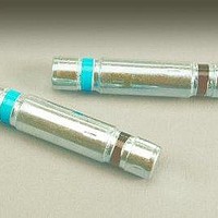
HOLDER MOUNT FOR GAS TUBE SL1026
Manufacturer
Littelfuse Inc
Series
SL1053Br
Specifications of SL1053B-NL
Accessory Type
Mounting Clip
Termination Style
Clip
Dimensions
14 mm D x 49 mm L
Technology
Mounting Clip Accessory for SL1026 Gas Plasma Arrester
Lead Free Status / RoHS Status
Lead free / RoHS Compliant
For Use With/related Products
GDT; SL1026
Lead Free Status / RoHS Status
Lead free / RoHS Compliant, Lead free / RoHS Compliant
Other names
SL1053B-NL


NOTES:
End of life limits
-- DC: 50% of minimum initial DC breakdown voltage limit to 150% of maximum initial
-- Impulse: less that 150% of initial impulse breakdown voltage limit.
1. Total current through center electrode, tested using SL1053B-NL holder
2. Exceeds capability of SL1053B-NL holder
©2009 Littelfuse, Inc.
Specifications are subject to change without notice.
Refer to www.littelfuse.com/series/SL1026.html for current information.
SL1026-275
SL1026-400
SL1026-700
Part Number*
Agency Approvals
3 Electrode GDT Graphical Symbol
Electrical Characteristics
DC breakdown voltage limit.
AGENCY
®
a
SL1026 Series Gas Plasma Arrester
e
MIN
200
300
560
DC Voltage
100 V/sec
MAX
350
500
840
AGENCY FILE NUMBER
b
E128662
Voltage
1kV/μs
1300
800
900
DC
a = TIP
b = RING
e = GROUND
(centre electrode)
@50-60Hz
Gas Plasma Arrester (GDT) Products
SL1026 Series
9 cycles
Current
(Amps)
1
200
200
200
AC
1 sec x10
Current
(Amps)
Revised: October 23, 2009
50Hz
1
AC
10
10
10
33
• RoHS compliant
• 55 kA surge capability
• 40 kA surge capability
• Will protect against
• Signaling equipment.
• Communication
• Control gear.
8/20μSec
(kAmps)
Features
Current
Description
The SL1026 Series is a heavy-duty transient
suppresser using Gas Plasma technology. In
response to transients that exceed the device's
breakover voltage, the device changes from a very
high impedance state to a low impedance state to
conduct harmful current away from the protected
system. The SL1026 is designed to protect electrical
and electronic equipment such as communications,
control and railway systems. Carefully designed
geometry ensures against short circuiting if a failure
occurs due to conditions and events beyond the
design criteria. Optional electrical mounting clip (part
SL1053 ) is available to aid mounting and connection.
Applications
1
(single shot) tested with
8/20μS pulse as defined
by IEC 61000-4-5
(repetitive)
Trapezoidal waveforms
as specified in RIA 12.
equipment
Surge
x 10
20
20
20
8/20μSec
(kAmps)
1,2
Single
Surge
Max
40
40
40
1
10/350μSec
Max Single
(kAmps)
Surge
8
8
8
• Will protect against
• Will protect against
• Trackside cabinets.
• Cell phone base
capacitor discharge
voltage transient
waveforms as specified
in RIA 12.
double exponential
voltage transient
waveforms as specified
in IEC 571.
stations
1
150(+) and 150(-)
10/1000μSec
(Amps)
200
200
200
SL1026 Series
®
Related parts for SL1053B-NL
Image
Part Number
Description
Manufacturer
Datasheet
Request
R

Part Number:
Description:
NTC Thermistor
Manufacturer:
Ametherm
Datasheet:

Part Number:
Description:
NTC Thermistor
Manufacturer:
Ametherm
Datasheet:
Part Number:
Description:
NTC Thermistor
Manufacturer:
Ametherm
Datasheet:
Part Number:
Description:
NTC Thermistor
Manufacturer:
Ametherm
Datasheet:
Part Number:
Description:
NTC Thermistor
Manufacturer:
Ametherm
Datasheet:
Part Number:
Description:
NTC Thermistor
Manufacturer:
Ametherm
Datasheet:
Part Number:
Description:
NTC Thermistor
Manufacturer:
Ametherm
Datasheet:
Part Number:
Description:
NTC Thermistor
Manufacturer:
Ametherm
Datasheet:
Part Number:
Description:
NTC Thermistor
Manufacturer:
Ametherm
Datasheet:
Part Number:
Description:
NTC Thermistor
Manufacturer:
Ametherm
Datasheet:

Part Number:
Description:
FUSEHOLDER 20A MINI INLINE CRIMP
Manufacturer:
Littelfuse Inc
Datasheet:

Part Number:
Description:
FUSEHOLDER BODY ATO INLINE PNLMT
Manufacturer:
Littelfuse Inc
Datasheet:

Part Number:
Description:
FUSE 2A 63V FAST 1206
Manufacturer:
Littelfuse Inc
Datasheet:
Part Number:
Description:
FUSE 1.25A 63V FAST 1206
Manufacturer:
Littelfuse Inc
Datasheet:
Part Number:
Description:
FUSE .250A 125V FAST 1206
Manufacturer:
Littelfuse Inc
Datasheet:
SL1053B-NL Summary of contents
Page 1
... DC: 50% of minimum initial DC breakdown voltage limit to 150% of maximum initial DC breakdown voltage limit. -- Impulse: less that 150% of initial impulse breakdown voltage limit. 1. Total current through center electrode, tested using SL1053B-NL holder 2. Exceeds capability of SL1053B-NL holder ©2009 Littelfuse, Inc. Specifications are subject to change without notice. ...
Page 2
Gas Plasma Arrester (GDT) Products Voltage vs. Time Characteristic Max dynamic breakover voltage Hold-over voltage On-State voltage 0 200 400 600 800 Time (ns) Electrical Specifications Insulation > 10GΩ at 100 Volts Resistance Capacitance: <=2.5pf, 1MHz 0 Volts Bias <150mS, ...