CA2-B0-34-615-121-D Carling Technologies, CA2-B0-34-615-121-D Datasheet - Page 7
CA2-B0-34-615-121-D
Manufacturer Part Number
CA2-B0-34-615-121-D
Description
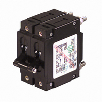
CIRCUIT BREAKER MAGNETIC 15A
Manufacturer
Carling Technologies
Series
Cr
Datasheet
1.CA2-B0-34-610-121-D.pdf
(22 pages)
Specifications of CA2-B0-34-615-121-D
Breaker Type
Hydraulic-Magnetic
Voltage
125VDC, 240VAC
Current - Trip (it)
15A
Number Of Poles
2
Actuator Type
Lever
Mounting Type
Panel Mount
Product Type
Circuit Breakers
Current Rating
15 Amps
Voltage Rating
277 VoltsAC / 80 Volts DC
Trip Time
0.6 s to 20 s
Mounting Style
Screw
Termination Style
Screw
Circuit Function
Series Trip (Current)
Color
Black
Dielectric Strength
1.96 KV
Features
American Standard or metric threaded stud terminals
Illuminated
No
Length
52.37 mm
Product
Hydraulic Magnetic Circuit Breakers
Width
19.18 mm
Lead Free Status / RoHS Status
Lead free / RoHS Compliant
Other names
432-1021


80
C-Series Handle Parallel Pole UL489A Listed – Ordering
1
Series
Notes:
1
2
3
C
1 SERIES
C
2 ACTUATOR
A
S
T
3 POLES
2
4 CIRCUIT
P
5 AUXILIARY/ALARM SWITCH
0
2
3
4
6 FREQUENCY & DELAY
D1
D2
7 CURRENT RATING (AMPERES)
811 110.000
812 120.000
912 125.000
813 130.000
Actuator Code:
A: Handle tie pin spacer(s) and retainers provided assembled with multi-pole units.
S: Handle moves to mid-position only upon electrical trip of the breaker.
T: Handle moves to mid-position and alarm switch activates only upon electrical trip of
the breaker.
Terminal Code:
3 & 6: Supplied with bus bars connecting the Line and Load Terminals.
A: Line and Load Terminals must be connected to a copper bus bar having a minimum
cross section of 0.078 square inches.
Above 200 amps, 3 poles are required.
Handle, one per pole
Mid-Trip Handle, one per pole
Mid-Trip Handle, one per pole & Alarm Switch
Series Trip (Parallel Pole)
w/o Aux Switch
S.P.D.T., 0.110 Q.C. Term.
S.P.D.T., 0.139 Solder Lug
S.P.D.T., 0.110 Q.C. Term.
(Gold Contacts)
DC Ultra Short
DC Short
2
Actuator
A 2
Two
3
1
3
Poles
814 140.000
815 150.000
816 160.000
817 170.000
—
4
Circuit
P 0
917 175.000
818 180.000
819 190.000
820 200.000
3
5
6
7
8
9
D4
D6
5
Aux/Alarm
Switch
S.P.S.T., 0.110 Q.C. Term.
(Gold Contacts)
S.P.S.T., 0.139 Solder Lug
S.P.S.T., 0.110 Q.C.
Term.(Gold Contacts)
S.P.S.T., 0.187 Q.C. Term.
S.P.D.T., 0.187 Q.C. Term.
DC Medium
DC Long
Three
—
6
Frequency
& Delay
922
825
D4
3
3
225.000
250.000
—
7
Current Rating
820
8 TERMINAL
3
6
A
9 ACTUATOR COLOR
White
Black
Red
Green
Blue
Yellow
Gray
Orange
10 MOUNTING
1
2
11 MAXIMUM APPLICATION RATING
M
12 AGENCY APPROVAL
T
K
UL489A Listed (up to 250 amps)
UL489A Listed, VDE Certified (up to 200 amps)
1/4 - 20 Threaded Stud
M6 Threaded Stud
Plug-In Stud
MOUNTING STYLE
Threaded Insert
6-32 x 0.195 inches
ISO M3 x 5mm
80 DC
2
—
LEGEND
ON-OFF
B
D
G
J
L
N
Q
S
8
Terminal
3 2 1
9
Actuator
Color
Dual
1
2
3
4
5
6
7
8
10
Mounting
Legend Color
Black
White
White
White
White
Black
Black
Black
www.carlingtech.com
—
11
Max. App.
Rating
M
12
Agency
Approval
T
Related parts for CA2-B0-34-615-121-D
Image
Part Number
Description
Manufacturer
Datasheet
Request
R

Part Number:
Description:
CIRCUIT BREAKER MAGNETIC 10A
Manufacturer:
Carling Technologies
Datasheet:

Part Number:
Description:
CIRCUIT BREAKER MAGNETIC 20A
Manufacturer:
Carling Technologies
Datasheet:

Part Number:
Description:
CIRCUIT BREAKER MAGNETIC 30A
Manufacturer:
Carling Technologies
Datasheet:

Part Number:
Description:
Circuit Breakers 50 A TWO POLE
Manufacturer:
Carling Technologies
Datasheet:
Part Number:
Description:
Circuit Breakers 5 A TWO POLE
Manufacturer:
Carling Technologies
Datasheet:
Part Number:
Description:
Circuit Breakers 40 A TWO POLE
Manufacturer:
Carling Technologies
Datasheet:
Part Number:
Description:
Circuit Breakers 30 A TWO POLE
Manufacturer:
Carling Technologies
Datasheet:

Part Number:
Description:
LIGHT INDICATOR GRN 12VDC PNLMNT
Manufacturer:
Carling Technologies
Part Number:
Description:
CONTURA ILL INDICATOR 12V RED
Manufacturer:
Carling Technologies
Part Number:
Description:
Current Regulator Diodes CURRENT REGULATOR DIODES 3.6mA
Manufacturer:
Carling Technologies
Part Number:
Description:
Rocker Switches
Manufacturer:
Carling Technologies
Datasheet: