MS3102R14S-9P Amphenol Industrial Operations, MS3102R14S-9P Datasheet - Page 26
MS3102R14S-9P
Manufacturer Part Number
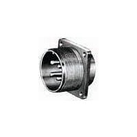
MS3102R14S-9P
Description
CONN RCPT 2POS BOX MNT W/PINS
Manufacturer
Amphenol Industrial Operations
Series
Military, MIL-DTL-5015r
Datasheet
1.MS3106R10SL-3S.pdf
(73 pages)
Specifications of MS3102R14S-9P
Connector Type
Receptacle, Male Pins
Mounting Type
Panel Mount, Flange
Number Of Positions
2
Termination
Solder Cup
Orientation
N (Normal)
Fastening Type
Threaded
Shell Material, Finish
Aluminum, Olive Drab Cadmium Plated
Shell Size - Insert
14S-9
Ingress Protection
Environment Resistant
Connector Body Material
Aluminum Alloy
Gender
Receptacle
Contact Gender
Pin
Connector Mounting
Box
Connector Shell Size
14S
Insert Arrangement
14S-9
Lead Free Status / RoHS Status
Contains lead / RoHS non-compliant
Features
-
Shell Size, Military
-
Lead Free Status / RoHS Status
Contains lead / RoHS non-compliant, Contains lead / RoHS non-compliant


MS/Standard
insert alternate positioning
To avoid cross-plugging problems in applications
requiring the use of more than one connector of the
same size and arrangement, alternate rotations are
available as indicated in the accompanying charts.
As shown in the diagram below, the front face of the pin
insert is rotated within the shell in a clockwise direction
from the normal shell key. The socket insert would be
rotated counter-clockwise the same number of degrees
in respect to the normal shell key.
Arrangement
Position W
10SL-4
12S-3
14S-2
14S-5
14S-7
14S-9
16-9
16-10
16-11
16-13
16S-1
16S-4
16S-5
16S-6
16S-8
18-1
18-3
18-4
18-8
18-10
18-11
18-12
18-15
18-20
18-22
18-29
20-3
20-4
20-5
20-6
20-15
20-17
20-18
20-19
20-21
Insert
View looking into front face of pin insert or rear of socket insert.
63
70
90
70
35
90
35
35
80
35
70
90
70
35
35
70
80
90
70
90
70
45
35
70
80
90
35
90
35
W
–
–
–
–
–
–
Position X
145
120
110
180
145
110
180
110
110
110
145
180
170
145
110
110
120
170
120
180
145
180
145
110
110
145
180
110
180
110
X
–
–
–
–
–
Degrees
215
240
270
215
250
270
250
250
250
215
270
265
215
250
250
240
265
240
270
215
270
215
250
250
215
270
250
270
250
Y
–
–
–
–
–
–
Position Y
290
290
325
325
325
280
325
290
290
325
325
290
280
290
290
325
290
280
325
325
Z
–
–
–
–
–
–
–
–
–
–
–
–
–
–
–
Arrangement
20-23
20-24
20-27
20-29
22-1
22-2
22-4
22-5
22-8
22-9
22-10
22-11
22-13
22-20
22-22
22-23
22-27
22-28
22-63
24-2
24-9
24-10
24-11
24-22
24-27
28-2
28-3
28-5
28-6
28-7
28-12
28-18
28-22
28-AY
32-2
Insert
Position Z
35
35
35
80
35
70
35
35
35
70
35
35
35
35
35
80
80
20
80
35
80
35
45
80
35
70
35
70
35
90
70
70
45
70
W
–
25
110
110
110
110
145
110
110
110
145
110
110
110
110
110
110
110
110
110
145
110
145
110
180
145
145
110
145
The following insert arrangements have the same alter-
nate insert rotations for W, X, Y and Z, which are:
X
–
–
–
–
–
–
–
–
Degrees
16-7
18-5
18-9
18-13
18-14
20-7
20-8
20-9
20-12
20-14
20-16
20-20
250
250
250
250
215
250
250
250
215
250
250
250
250
250
250
250
250
250
250
250
215
250
215
250
270
215
215
250
215
Y
–
–
–
–
–
–
325
325
325
280
325
290
325
325
325
290
325
325
325
325
280
280
280
325
280
325
280
325
290
325
290
325
290
290
290
20-22
22-6
22-12
22-14
22-15
22-16
22-17
22-18
22-19
22-21
22-24
22-25
Z
–
–
–
–
–
–
80
W
Arrangement
22-29
22-33
22-34
24-1
24-3
24-4
24-5
24-6
24-7
24-12
24-14
24-16
110
32-5
32-7
32-8
32-14
32-15
32-17
32-25
32-48
32-64
32-68
32-82
36-3
36-4
36-5
36-6
36-9
36-10
36-14
36-15
36-AF
40-1
40-5
40-9
40-10
40-35
40-AD
40-AG
40-AP
40-AV
X
Insert
Degrees
24-17
24-20
24-21
24-28
28-1
28-4
28-8
28-9
28-10
28-11
28-14
28-15
250
Y
35
80
80
65
35
45
60
80
80
30
30
70
70
35
80
80
90
60
65
65
33
65
65
70
45
37
35
90
W
–
28-16
28-17
28-19
28-20
28-21
32-1
32-3
32-4
32-6
32-9
32-10
32-12
280
Z
110
125
125
130
110
110
120
100
145
145
120
110
125
125
180
125
130
125
125
130
110
180
74
X
–
–
–
–
–
–
Degrees
32-13
32-22
32-AF
36-1
36-7
36-8
36-13
40-AR
40-AS
40-AT
40-AU
250
235
235
230
250
250
110
215
215
240
250
235
235
270
245
235
225
225
230
285
250
270
Y
–
–
–
–
–
–
–
325
280
280
295
280
250
290
290
325
280
280
305
300
270
310
310
290
322
325
Z
–
–
–
–
–
–
–
–
–
–
Related parts for MS3102R14S-9P
Image
Part Number
Description
Manufacturer
Datasheet
Request
R

Part Number:
Description:
CONN RECEPT 10POS BOX MNT W/PINS
Manufacturer:
Amphenol Industrial Operations
Datasheet:

Part Number:
Description:
CONN RECEPT 14POS BOX MNT W/PINS
Manufacturer:
Amphenol Industrial Operations

Part Number:
Description:
CONN RECEPT 9POS BOX MNT W/PINS
Manufacturer:
Amphenol Industrial Operations

Part Number:
Description:
CONN RCPT 5POS BOX MNT W/PINS
Manufacturer:
Amphenol Industrial Operations
Part Number:
Description:
ER 6C 4#16 2#12 PIN RECP BOX
Manufacturer:
Amphenol Industrial Operations

Part Number:
Description:
JAM NUT CONN, RCPT, SIZE 9, 6POS, PANEL
Manufacturer:
Amphenol Industrial Operations
Datasheet:
Part Number:
Description:
PT 41C 41#20 PIN RECP
Manufacturer:
Amphenol Industrial Operations
Part Number:
Description:
PT 41C 41#20 SKT RECP
Manufacturer:
Amphenol Industrial Operations