MS3116F8-2P Amphenol Industrial Operations, MS3116F8-2P Datasheet - Page 32
MS3116F8-2P
Manufacturer Part Number
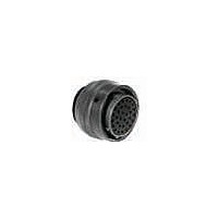
MS3116F8-2P
Description
CONN PLUG 2POS STRAIGHT W/PINS
Manufacturer
Amphenol Industrial Operations
Series
Military, MIL-C-26482 Series Ir
Type
Cable Plugr
Specifications of MS3116F8-2P
Connector Type
Plug, Male Pins
Features
Strain Relief
Mounting Type
Free Hanging (In-Line)
Number Of Positions
2
Termination
Solder Cup
Orientation
N (Normal)
Fastening Type
Bayonet Lock
Shell Material, Finish
Aluminum, Olive Drab Cadmium Plated
Shell Size - Insert
8-2
Ingress Protection
Environment Resistant
Connector Body Material
Aluminum
Gender
Plug
Contact Gender
Pin
Connector Mounting
Cable
Connector Shell Size
8
Insert Arrangement
8-2
Agency Approvals
UL Recognized
Angle
Straight
Application
True MIL
Brand/series
MS Series
Class
F
Contact Configuration
2#20
Contact Plating
Gold
Contact Size
20
Contact Type
Pin
Current, Rating
7.5 A
Finish, Housing
Olive Drab Cadmium
Housing Type
Metal
Material, Dielectric
Neoprene
Material, Housing
Aluminum
Mating Type
Bayonet
Number Of Contacts
2
Primary Type
26482 MIL Spec
Shell Size
8
Special Features
5 Key/Keyway Polarization
Strain Relief
External
Voltage, Rating
600 VAC
Wire, Awg
20
Lead Free Status / RoHS Status
Lead free by exemption / RoHS compliant by exemption
Shell Size, Military
-
Lead Free Status / RoHS Status
Contains lead / RoHS non-compliant, Lead free by exemption / RoHS compliant by exemption


PT00 SE (MS3120)
SP00 SE
wall mounting receptacle
* Back panel mounting
All dimensions for reference only.
To complete part number see how to order on page 39.
■
Shell
Shell
Size
10
12
14
16
18
20
22
24
Size
10
12
14
16
18
20
22
24
(MMC) located within .005 of (TP)
8
8
1.062
1.156
1.250
1.375
.594
.719
.812
.906
.969
PT
A
M
1.328
1.328
1.328
1.328
1.328
1.328
1.359
1.359
1.422
Max.
PT00SE-XX-XXX
SP00SE-XX-XXX
MS3120E-XX-XXX
Class “SE”, MS / “E”
“SE” Open Wire Seal
L
(TP)
R
L
1.031
1.125
1.203
1.297
1.375
1.500
.812
.938
SP
–
K
Receptacle Front View
1.080
1.204
1.330
1.454
1.580
N Dia.
Max
N
.560
.704
.825
.954
1.047
1.141
1.234
1.328
1.453
1.578
1.703
PT
.828
.954
Max.
S
1.141
1.266
1.360
1.453
1.532
1.688
1.766
1.891
SP
–
Dia.
.125
.188
.312
.375
.500
.625
.625
.750
.800
G
Class “SE” (SR), MS / “F”
.120
.120
.120
.120
.120
.120
.120
.120
.147
“SE” (SR), MS / “F” Strain Relief
TERMINATION ASSEMBLIES
PT
M
A
± .005
T Dia.
PT00SE-XX-XXX (SR)
SP00SE-XX-XXX (SR)
MS3120F-XX-XXX
2.422
2.422
2.422
2.422
2.537
2.537
2.824
2.824
2.900
Max.
.150
.150
.150
.150
.150
.150
.150
.150
L
SP
–
(TP)
30
S
R
K
L
A Dia.
+.001
1.000
1.125
1.250
1.375
1.500
–.005
.473
.590
.750
.875
(TP)
R
1.094
1.156
1.406
1.406
1.594
1.688
Max.
.781
.844
.969
S
G
N
T Dia.
4 Holes
±.016
N
.062
.062
.062
.062
.062
.062
.094
.094
.094
K
Receptacle Side View
1.034
1.159
1.284
D Dia.
Max.
.444
.558
.683
.808
.909
.431
.431
.431
.431
.431
.431
.556
.556
.589
–
PT
+.010
–.000
M
Class “SP”, MS / “P”
PT00SP-XX-XXX
SP00SP-XX-XXX
“SP” Potting Boot
A
M
.462
.462
.462
.462
.462
.556
.556
.589
SP
–
1.656
1.656
1.656
1.656
1.656
1.750
1.750
1.782
Max.
L
–
L
Max. Panel Thickness
K
.094
.094
.094
.094
.094
.094
.219
.219
.219
PT
D
P*
N
1.110
1.234
1.360
1.484
1.610
N Dia.
Max.
.734
.858
.984
–
.125
.125
.125
.125
.125
.219
.219
.219
SP
–
Related parts for MS3116F8-2P
Image
Part Number
Description
Manufacturer
Datasheet
Request
R

Part Number:
Description:
CONN PLUG 4POS W/PINS SOLDER
Manufacturer:
Amphenol Industrial Operations

Part Number:
Description:
CONN PLUG 6POS W/PINS SOLDER
Manufacturer:
Amphenol Industrial Operations

Part Number:
Description:
CONN PLUG 3POS W/SOCKET SOLDER
Manufacturer:
Amphenol Industrial Operations

Part Number:
Description:
CONN PLUG 4POS W/SOCKET SOLDER
Manufacturer:
Amphenol Industrial Operations

Part Number:
Description:
CONN PLUG 2POS W/SOCKET SOLDER
Manufacturer:
Amphenol Industrial Operations

Part Number:
Description:
JAM NUT CONN, RCPT, SIZE 9, 6POS, PANEL
Manufacturer:
Amphenol Industrial Operations
Datasheet:

Part Number:
Description:
PT 41C 41#20 PIN RECP
Manufacturer:
Amphenol Industrial Operations
Part Number:
Description:
PT 41C 41#20 SKT RECP
Manufacturer:
Amphenol Industrial Operations