MS3126F18-32P Amphenol Industrial Operations, MS3126F18-32P Datasheet - Page 38
MS3126F18-32P
Manufacturer Part Number
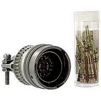
MS3126F18-32P
Description
CONN PLUG 32POS STRAIGHT W/PINS
Manufacturer
Amphenol Industrial Operations
Series
Military, MIL-C-26482 Series Ir
Type
Cable Plugr
Specifications of MS3126F18-32P
Connector Type
Plug, Male Pins
Features
Strain Relief
Mounting Type
Free Hanging (In-Line)
Number Of Positions
32
Termination
Crimp
Orientation
N (Normal)
Fastening Type
Bayonet Lock
Shell Material, Finish
Aluminum, Olive Drab Cadmium Plated
Shell Size - Insert
18-32
Ingress Protection
Environment Resistant
Connector Body Material
Aluminum
Gender
Plug
Contact Gender
Pin
Connector Mounting
Cable
Connector Shell Size
18
Insert Arrangement
18-32
Angle
Straight
Application
True MIL
Brand/series
MS Series
Class
F
Contact Configuration
32#20
Contact Plating
Gold
Contact Type
Pin
Current, Rating
7.5 A
Finish, Housing
Olive Drab Cadmium
Housing Type
Metal
Material, Dielectric
Neoprene
Material, Housing
Aluminum
Mating Type
Bayonet
Number Of Contacts
32
Primary Type
26482 MIL Spec
Shell Size
18
Special Features
Rear Insertable/Front Release, 5 Key/Keyway Polarization
Strain Relief
External
Voltage, Rating
600 V
Wire, Awg
20
Lead Free Status / RoHS Status
Lead free by exemption / RoHS compliant by exemption
Shell Size, Military
-
Lead Free Status / RoHS Status
Contains lead / RoHS non-compliant, Lead free by exemption / RoHS compliant by exemption


PT07 SE (MS3124)
SP07 SE
jam nut receptacle
J
“SE”, MS / “E” Open Wire Seal
To complete part number see how to order on page 39.
All lockwire holes are .044 Dia. Min.
All dimensions for reference only.
A
PT07SE-XX-XXX
SP07SE-XX-XXX
MS3124E-XX-XXX
Shell
Shell
Size
Size
10
12
14
16
18
20
22
24
10
12
14
16
18
20
22
24
8
8
P
R
M
K
L
Class “SE”, MS / “E”
H Hex
1.079
1.205
1.329
1.455
1.579
1.705
1.829
Receptacle Front
Max.
Max.
1.438
1.438
1.438
1.438
1.438
1.438
1.625
1.625
1.688
.767
.892
L
View
N
1.078
1.266
1.391
1.516
1.641
1.828
1.954
2.078
Max.
.954
Max.
1.124
1.249
1.374
1.530
1.655
1.780
S
.749
.874
.999
N
1.000
1.125
1.250
1.375
1.500
A Dia.
+.001
–.005
.473
.590
.750
.875
Min.
.234
.297
.422
.547
.609
.734
.734
.922
.984
F
J
“SE” (SR), MS / “F” Strain Relief
TERMINATION ASSEMBLIES
A
1.066
1.191
1.316
1.441
1.566
Class “SE” (SR), MS / “F”
J Flat
+.000
–.010
.530
.655
.818
.942
PT07SE-XX-XXX (SR)
SP07SE-XX-XXX (SR)
MS3124F-XX-XXX
G Dia.
R
Free
P
.125
.188
.312
.375
.500
.625
.625
.750
.800
M
K
+.011
–.010
36
L
.125
.125
.125
.125
.125
.125
.156
.156
.156
S
H
K
Max.
1.922
1.922
1.922
1.922
2.000
2.000
2.172
2.172
2.234
L
Receptacle Side View
±.005
.696
.696
.696
.696
.696
.696
.884
.884
.917
M
F
S
N
Max.
1.016
1.141
1.203
1.469
1.469
1.656
1.750
.828
.891
N
Panel Thickness
Min.
.062
.062
.062
.062
.062
.062
.062
.062
.062
P
1.034
1.159
1.284
Dia.
.444
.558
.683
.808
.909
G
–
Max.
.125
.125
.125
.125
.125
.125
.250
.250
.250
Class “SP”, MS /”P”
“SP”, MS / “P” Potting Boot
J
A
PT07SP-XX-XXX
SP07SP-XX-XXX
MS3124P-XX-XXX
Max.
1.656
1.656
1.656
1.656
1.656
1.922
1.922
1.951
1.0000-20 UNEF
1.1250-18 NEF
1.2500-18 NEF
1.3750-18 NEF
1.5000-18 NEF
1.6250-18 NEF
.5625-24 UNEF
.6875-24 NEF
.8750-20 UNEF
L
–
R
P
M
Class 2A
K
Thread
R
L
N Dia.
1.110
1.234
1.360
1.484
1.610
Max.
.734
.858
.984
–
G
N
Related parts for MS3126F18-32P
Image
Part Number
Description
Manufacturer
Datasheet
Request
R

Part Number:
Description:
CONN PLUG 10POS W/SOCKET CRIMP
Manufacturer:
Amphenol Industrial Operations

Part Number:
Description:
CONN PLUG 10POS W/PINS CRIMP
Manufacturer:
Amphenol Industrial Operations

Part Number:
Description:
CONN PLUG 3POS W/SOCKET CRIMP
Manufacturer:
Amphenol Industrial Operations

Part Number:
Description:
CONN PLUG 18POS W/SOCKET CRIMP
Manufacturer:
Amphenol Industrial Operations
Datasheet:

Part Number:
Description:
CONN PLUG 5POS W/SOCKET CRIMP
Manufacturer:
Amphenol Industrial Operations

Part Number:
Description:
JAM NUT CONN, RCPT, SIZE 9, 6POS, PANEL
Manufacturer:
Amphenol Industrial Operations
Datasheet:

Part Number:
Description:
PT 41C 41#20 PIN RECP
Manufacturer:
Amphenol Industrial Operations
Part Number:
Description:
PT 41C 41#20 SKT RECP
Manufacturer:
Amphenol Industrial Operations