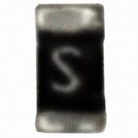
SF-0402S200-2 Bourns Inc., SF-0402S200-2 Datasheet - Page 2

SF-0402S200-2
Manufacturer Part Number
SF-0402S200-2
Description
FUSE 2.0A SLOW SMD 0402
Manufacturer
Bourns Inc.
Series
SinglFuse™ SFr
Type
Slow Blowr
Datasheet
1.SF-0402S200-2.pdf
(4 pages)
Specifications of SF-0402S200-2
Fuse Type
Slow Blow, Time Lag
Voltage - Rated
24VDC
Current
2A
Package / Case
0402 (1005 Metric)
Size / Dimension
0.040" L x 0.020" W x 0.014" H (1.00mm x 0.50mm x 0.35mm)
Mounting Type
Surface Mount
Operating Temperature
-40°C ~ 105°C
Dc Cold Resistance
0.024 Ohm
Melting I²t
0.0404
Current Rating
2 Amps
Voltage Rating
24 Volts
Fuse Size / Group
0402
Termination Style
SMD/SMT
Body Material
Ceramic
Dimensions
1 mm L x 0.52 mm W
Product
Surface Mount Fuse
Interrupt Rating
35 Amps
Mounting Style
SMD/SMT
Operating Temperature Range
- 20 C to + 120 C
Resistance
24 mOhms
Voltage Rating Vdc
24V
Fuse Current
2A
Breaking Capacity
35A @ 24VDC
Blow Characteristic
Slow Blow
Fuse Case Style
402
Svhc
No SVHC (15-Dec-2010)
Approval Category
UL Recognised
Rohs Compliant
Yes
Lead Free Status / RoHS Status
Lead free / RoHS Compliant
Color
-
Lead Free Status / Rohs Status
Lead free / RoHS Compliant
Other names
SF-0402S200-2TR
■
■
■
■
■
■
SinglFuse
PACKAGING: 10,000 pcs./reel
Operating Temperature ................................................................................. -40 °C to +105 °C
Storage Conditions
Solder Refl ow Recommendations
Product Dimensions
Thermal Derating Curve
Portable memory
LCD monitors
Disk drives
PDAs
Digital cameras
DVDs
Temperature ............................................................................................... +5 °C to +35 °C
Humidity .........................................................................................................40 % to 75 %
Shelf Life ...........................................................................2 years from manufacturing date
250
200
150
100
SF-0402S Series - Slow Blow Surface Mount Fuses
50
(.008 ± .004)
0.2 ± 0.1
™
(.039 ± .004)
SF-0402S Series Applications
120
110
100
1.0 ± 0.1
90
80
-20
(.008 ± .004)
180 °C
150 °C
0.2 ± 0.1
0
AMBIENT TEMPERATURE (°C)
20
(.020 ± .002)
PRE-HEATING ZONE
0.52 ± 0.05
90 ± 30 Seconds
HEATING TIME
Peak: 250 +0/-5 °C
40
230 °C or higher
■
■
■
■
■
Cell phones
Rechargeable battery packs
Battery chargers
Set top boxes
Industrial controllers
30 ± 10 Seconds
60
DIMENSIONS:
(.010 ± .004)
0.25 ± 0.1
80
SOLDERING ZONE
100
(.010 ± .004)
0.25 ± 0.1
(INCHES)
MM
(.014 ± .002)
120
0.35 ± 0.05
Customers should verify actual device performance in their specifi c applications.
PEAK: 250 +0/-5 °C, 5 seconds
PRE-HEATING ZONE: 150 to 180 °C, 90 ± 30 seconds
SOLDERING ZONE: 230 °C or higher, 30 ± 10 seconds
Sn PLATING
Recommended Pad Layout
Construction & Material Content
Specifi cations are subject to change without notice.
CERAMIC SUBSTRATE
(.015)
0.381
(.061)
1.55
FUSE ELEMENT
OVERCOAT
Cu / Ni PLATING
(.022)
0.558


