HR10-10P-12S Hirose Electric Co Ltd, HR10-10P-12S Datasheet - Page 11
HR10-10P-12S
Manufacturer Part Number
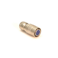
HR10-10P-12S
Description
PLUG W/SOCKET INSERT (12 CON)
Manufacturer
Hirose Electric Co Ltd
Series
HR10r
Datasheet
1.HR10-10R-C.pdf
(20 pages)
Specifications of HR10-10P-12S
Connector Type
Plug, Female Sockets
Number Of Positions
12
Shell Size - Insert
10
Mounting Type
Free Hanging (In-Line)
Termination
Solder
Fastening Type
Push-Pull
Orientation
Keyed
Shell Material, Finish
Brass and Zinc, Nickel Plated
Lead Free Status / RoHS Status
Contains lead / RoHS non-compliant
Features
-
Ingress Protection
-
Shell Size, Military
-
Other names
*HR10-10P-12S
HR105
HR105
Available stocks
Company
Part Number
Manufacturer
Quantity
Price
Company:

Part Number:
HR10-10P-12S(73)
Manufacturer:
HIROSEEL
Quantity:
19


■Cable connecting methods
1.Cable end treatment
2. Soldering male pin to cable center
Fig.1
1. Dimensions for cable end treatment are shown in
2.Termination is described below.
Fig.2
1. Solder male pin to cable center conductor as
conductor.
(1). Pre-solder the solder pot of pin with Ø0.5mm
(2). Male pin should fit flush against the cable
(3). Remove any excess solder from the pin with a
(4). A properly soldered terminal will yield 500gf
Fig 1.
(1).Strip cable outer jacket as indicated.
(2).Slit outer jacket on both sides per Fig.1.
(3).Fold back outer cover.
(4).Remove insulator from cable.
indicated in Fig.2.
string solder.
insulator as shown.
knife.This surface must be smooth.
when stretched.
2 pieces (180° reverse side)
Should fix flush
Contact fixing jig
such as vise
Malu pin or Female pin
Slit cable outer jaket
Soldering
(2.5)
11±0.5
3.7±0.2
1.4±0.2
HR10B-2.5CP
HR10B-2.5CJ
3.Crimping cable outer conductor
Fig.3
1. Insert cable prepared per PROCESS 2 into the
2. Crimp this installed metal clamp with tool HR10-
connector.The cable should be inserted until it
comes to a full stop.This may be verified by
checking the dimension from the side of the
connector to the top of the contact(as indicated in
Fig 3). This dimension should be A.
TC-01 per Fig.3 and remove excess insulation with
a knife.
It is possible to pull back the contact.
Hold cable when crimping metal clamp and keep
the dimension to show in Fig 3. after crimping metal
clamp.
(HR10B-2.5CP)
Clamp metal
Table 1 dimenshion A
1.5±0.2mm
2.5CP
Remove excess insulator
material (remaining after
clamping is complated)
with a knife or aimilarobject.
HR10 Series●Push-Pull Connectors
0
2.5CJ
+0.3
0
A
mm
Connector
189
Related parts for HR10-10P-12S
Image
Part Number
Description
Manufacturer
Datasheet
Request
R

Part Number:
Description:
PLUG W/PIN INSERT (12 CONTACT)
Manufacturer:
Hirose Electric Co Ltd
Datasheet:

Part Number:
Description:
PLUG W/SOCKET INSERT (12 CON)
Manufacturer:
Hirose Electric Co Ltd
Datasheet:
Part Number:
Description:
PLUG W/PIN INSERT (12 CONTACT)
Manufacturer:
Hirose Electric Co Ltd
Datasheet:

Part Number:
Description:
CONN DUST CAP FOR 10-12POS RECPT
Manufacturer:
Hirose Electric Co Ltd
Datasheet:

Part Number:
Description:
CONN RECEPT 12POS FEMALE DIP PCB
Manufacturer:
Hirose Electric Co Ltd
Datasheet:

Part Number:
Description:
Conn Rectangular PL 14 POS 2.54mm Crimp RA Cable Mount
Manufacturer:
Hirose Electric Co Ltd
Part Number:
Description:
Conn Shrouded Header HDR 10 POS 2mm Solder ST SMD Embossed T/R
Manufacturer:
Hirose Electric Co Ltd
Datasheet:
Part Number:
Description:
DF11-20DP-2DSA(24)
Manufacturer:
Hirose Electric Co Ltd
Datasheet:
Part Number:
Description:
Conn Shrouded Header HDR 6 POS 2mm Solder ST Thru-Hole Bag
Manufacturer:
Hirose Electric Co Ltd
Datasheet:
Part Number:
Description:
Conn Shrouded Header HDR 8 POS 2mm Solder ST Thru-Hole Tube
Manufacturer:
Hirose Electric Co Ltd
Datasheet:
Part Number:
Description:
Conn Shrouded Header HDR 26 POS 2mm Solder ST SMD
Manufacturer:
Hirose Electric Co Ltd
Datasheet:
Part Number:
Description:
Conn Shrouded Header HDR 22 POS 2mm Solder ST SMD
Manufacturer:
Hirose Electric Co Ltd
Part Number:
Description:
Conn Shrouded Header HDR 22 POS 2mm Solder ST SMD
Manufacturer:
Hirose Electric Co Ltd
Part Number:
Description:
2mm 22w Wire to Board IDC Crimp Connector
Manufacturer:
Hirose Electric Co Ltd