HR10A-7R-4SB Hirose Electric Co Ltd, HR10A-7R-4SB Datasheet - Page 18
HR10A-7R-4SB
Manufacturer Part Number
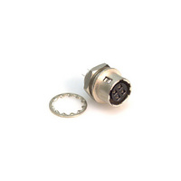
HR10A-7R-4SB
Description
CONN RECEPT 4POS FEMALE DIP
Manufacturer
Hirose Electric Co Ltd
Series
HR10Ar
Datasheet
1.HR10-10R-C.pdf
(20 pages)
Specifications of HR10A-7R-4SB
Connector Type
Receptacle, Female Sockets
Number Of Positions
4
Shell Size - Insert
7
Mounting Type
Panel Mount, Bulkhead; Through Hole
Termination
Solder
Fastening Type
Push-Pull
Orientation
Keyed
Shell Material, Finish
Brass and Zinc, Nickel Plated
Lead Free Status / RoHS Status
Contains lead / RoHS non-compliant
Features
-
Ingress Protection
-
Shell Size, Military
-
Other names
*HR10A-7R-4SB
HR351
HR351


196
HR10 Series●Push-Pull Connectors
■Connection work procedure(plug side)
For any question on using the plugs, contact our sales or engineering department.
Remarks : Loctite 242, Henkel Japan or equivalent is recommend to prevent the male thread section of the P shell unit and the set screw
1
2
3
4
5
This applies also to the jack side connection work.
No special connection work procedure is given here for the receptacle side because no special procedure is
necessary.
Use cables with a nominal sectional area of 0.129 mm
After processing the cable ends according to the dimensions in the above drawings, fit the parts to the cable as shown in the drawings.
Fit the parts to the cable in the following order: tightener, clamp
washer, and plug body.
(solder type)
Insert the P shell unit into the assembly tool stand and solder it.
(crimp type)
After crimping the appropriate crimp terminal to the cable core, insert the crimp terminal into the terminal hole in the P shell unit.
Assemble the connector in the following steps.
1. Screw the plug body into the thread in the P shell unit with the
2. Apply the clamp washer to the bifurcated part of the plug body,
This completes the work.
tightening force shown in Table 1 using a torque wrench with a
fixed torque.
Before tightening the plug body,slacken part C so that no load is
applied to the soldered wires.
and then tighten the tightener until surface B touches the plug
body surface A.
Table 2 spanner jaw distance
for loosing.
Size 10
Size 13
Size 7
Size
About 2 for solder type
2
-0.5
0
for crimp type
HR10
11
––
P shell unit
8
P shell unit
HR10A
HR10 TYPE
7.5
9.5
13
About 2
A
Table 3 cable end processing dimensions
2 or more
Size 10
Size 13
D
Size 7
Size
C
Clamp
Dimension C
2
Plug body
5.5 or less
(AWG#26) at the finish outside diameters applicable for each size.
for HR10
7 or less
––
Boss
Solder type Crimp type
Dimension D for HR10A
Set screw
Fit the parts to the cable in the following order: cord bushing and
plug body.
1. Fix by caulking the clamp accompanying the cable with the cable
2. Screw the plug body into the thread in the P shell until with a
3. Tighten the set screw so that the tip of the screw presses one of
4.Attach the cord bushing to the plug body.
10
16
26
Bifurcated part
crimping tool(HR10A-TC-02)
tightening force shown in Table 1 using a torque wrench with a
fixed torque. Before tightening the plug body, slacken the part D so
that no load is applied to the soldered wires.
the two bosses on the clamp.
Fix the set screw with a tightening torque of 0.3N(3kg∙cm)
Plug body
Clamp washer
Face A
15-20
15-20
26
Spanner jaw distance
HR10A TYPE
Face B
Table 1
Size 10
Size 13
Size 7
Size
Tightener
Cord bushing
Spanner jaw distance
Tightening force
1.5N∙m(15kg∙cm)
2N∙m(20kg∙cm)
2N∙m(20kg∙cm)
Cable
Cable
Related parts for HR10A-7R-4SB
Image
Part Number
Description
Manufacturer
Datasheet
Request
R

Part Number:
Description:
CONN RECEPT 6POS FEMALE DIP
Manufacturer:
Hirose Electric Co Ltd
Datasheet:

Part Number:
Description:
CONN HR10A RECEPT 4POS FEMALE
Manufacturer:
Hirose Electric Co Ltd
Datasheet:

Part Number:
Description:
CONN HR10A RECEPT 6POS MALE
Manufacturer:
Hirose Electric Co Ltd
Datasheet:

Part Number:
Description:
CONN HR10A RECEPT 4POS MALE
Manufacturer:
Hirose Electric Co Ltd
Datasheet:
Part Number:
Description:
CONN HR10A RECEPT 6POS MALE
Manufacturer:
Hirose Electric Co Ltd
Datasheet:

Part Number:
Description:
Conn Rectangular PL 14 POS 2.54mm Crimp RA Cable Mount
Manufacturer:
Hirose Electric Co Ltd
Part Number:
Description:
Conn Shrouded Header HDR 10 POS 2mm Solder ST SMD Embossed T/R
Manufacturer:
Hirose Electric Co Ltd
Datasheet:
Part Number:
Description:
DF11-20DP-2DSA(24)
Manufacturer:
Hirose Electric Co Ltd
Datasheet:
Part Number:
Description:
Conn Shrouded Header HDR 6 POS 2mm Solder ST Thru-Hole Bag
Manufacturer:
Hirose Electric Co Ltd
Datasheet:
Part Number:
Description:
Conn Shrouded Header HDR 8 POS 2mm Solder ST Thru-Hole Tube
Manufacturer:
Hirose Electric Co Ltd
Datasheet:
Part Number:
Description:
Conn Shrouded Header HDR 26 POS 2mm Solder ST SMD
Manufacturer:
Hirose Electric Co Ltd
Datasheet:
Part Number:
Description:
Conn Shrouded Header HDR 22 POS 2mm Solder ST SMD
Manufacturer:
Hirose Electric Co Ltd
Part Number:
Description:
Conn Shrouded Header HDR 22 POS 2mm Solder ST SMD
Manufacturer:
Hirose Electric Co Ltd
Part Number:
Description:
2mm 22w Wire to Board IDC Crimp Connector
Manufacturer:
Hirose Electric Co Ltd