B82442A1222K EPCOS Inc, B82442A1222K Datasheet - Page 7
B82442A1222K
Manufacturer Part Number
B82442A1222K
Description
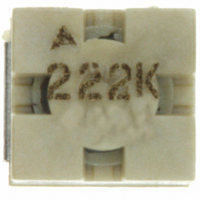
INDUCTOR 2.2UH 1300MA 2220 10%
Manufacturer
EPCOS Inc
Series
SIMIDr
Type
Ferrite Corer
Specifications of B82442A1222K
Inductance
2.2µH
Tolerance
±10%
Package / Case
2220 (5750 Metric)
Current
1.3A
Dc Resistance (dcr)
48 mOhm Max
Q @ Freq
10 @ 7.96MHz
Self Resonant Freq
42MHz
Mounting Type
Surface Mount
Frequency - Test
7.96MHz
Material - Core
Ferrite Drum
Applications
General Purpose
Core Material
Ferrite
Dimensions
5 mm W x 5.6 mm L
Test Frequency
7.96 MHz
Maximum Dc Current
1300 mAmps
Maximum Dc Resistance
0.048 Ohms
Self Resonant Frequency
42 MHz
Q Minimum
10
Operating Temperature Range
- 55 C to + 150 C
Termination Style
SMD/SMT
Inductance Tolerance
± 10%
Dc Resistance Max
0.048ohm
Dc Current Rating
1.3A
Inductor Case Style
2220
No. Of Pins
2
Svhc
No SVHC (18-Jun-2010)
Rohs Compliant
Yes
Lead Free Status / RoHS Status
Lead free / RoHS Compliant
Shielding
-
Current - Saturation
-
Current - Temperature Rise
-
Lead Free Status / Rohs Status
Lead free / RoHS Compliant
Other names
495-1774-2
B82442A1222K000
B82442A1222K000
Available stocks
Company
Part Number
Manufacturer
Quantity
Price
Company:

Part Number:
B82442A1222K000
Manufacturer:
EPCOS
Quantity:
60 000


Disturbed equipment
Electrical devices, equipment and/or systems subject to interference and which can be adversely
affected by it are termed disturbed equipment.
In the same way as interference sources, disturbed equipment can also be categorized correspond-
ing to frequency characteristics. A distinction can be made between narrowband and broadband
susceptibility
Narrowband systems include radio and TV sets, for example, whereas data processing systems are
generally specified as broadband systems.
Radio and TV receivers
Radio reception equipment
Modems
Data transmission systems
Telemetric radio transmission devices
Frequency-coded signalling equipment
Fig. 6
2.3
As previously mentioned, an interference source causes both conducted and radiated electro-
magnetic interference.
Propagation along lines can be detected by measuring the interference current and the interference
voltage
The effect of magnetic and electric interference fields on their immediate vicinity is assessed by
measuring the radiated magnetic and electric field components. This method of propagation is also
frequently termed electric or magnetic coupling (near field).
In higher frequency ranges, characterized by the fact that device dimensions are in the order of
magnitude of the wavelength under consideration, the interference energy is mainly radiated direct-
ly (far field).
Conducted and radiated propagation must also be taken into consideration when measuring the
susceptibility of disturbed equipment.
Interference sources e.g. sine-wave generators as well as pulse generators with a wide variety of
pulse shapes are used for such tests.
General Technical Information
(fig.
Propagation of electromagnetic interference and EMC measurement techniques
Narrowband susceptibility
Disturbed equipment
7).
(fig.
6).
Disturbed equipment (affected by EMI)
15
Digital and analog systems
Data processing systems
Process control computers
Control systems
Video transmission systems
Interface lines
04/00
Broadband susceptibility
Related parts for B82442A1222K
Image
Part Number
Description
Manufacturer
Datasheet
Request
R


Part Number:
Description:
CAP .15UF 63V METAL POLY
Manufacturer:
EPCOS Inc
Datasheet:


Part Number:
Description:
CAP .01UF 400V METAL POLY
Manufacturer:
EPCOS Inc
Datasheet:
