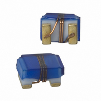
PE-0805CM561JTT PULSE ELECTRONICS CORPORATION, PE-0805CM561JTT Datasheet - Page 28

PE-0805CM561JTT
Manufacturer Part Number
PE-0805CM561JTT
Description
INDUCTOR WW RF 560NH 240MA 0805
Manufacturer
PULSE ELECTRONICS CORPORATION
Series
0805CMr
Type
Ceramicr
Datasheet
1.PE-0805CM561JTT.pdf
(30 pages)
Specifications of PE-0805CM561JTT
Inductance
560nH
Current
240mA
Tolerance
±5%
Dc Resistance (dcr)
3.1 Ohm Max
Q @ Freq
40 @ 100MHz
Self Resonant Freq
600MHz
Package / Case
0805 (2012 Metric)
Mounting Type
Surface Mount
Operating Temperature
-40°C ~ 125°C
Frequency - Test
100MHz
Material - Core
Ceramic
Applications
General Purpose
Maximum Dc Current
240 mAmps
Maximum Dc Resistance
3.1 Ohms
Self Resonant Frequency
340 MHz
Q Minimum
23
Termination Style
SMD/SMT
Dimensions
1.68 mm W x 2.29 mm L x 1.450 mm H
Shielding
Unshielded
Lead Free Status / RoHS Status
Lead free / RoHS Compliant
Shielding
-
Current - Saturation
-
Current - Temperature Rise
-
Lead Free Status / Rohs Status
Details
Other names
553-1047-2
PE0805CM561JTT
PE0805CM561JTT
WIRE-WOUND
RF CHIP INDUCTORS
Application Notes
www.pulseeng.com
The Inductor Basics
The effect of Cd can have a dramatic effect upon the impedance of the inductor as illustrated in Fig 2.0, because
"fringe" effects become dominant at high frequencies. At low frequencies the inductor's reactance parallels that of an
ideal inductor. With increasing frequency the reactance of the inductor departs from the ideal curve and increases at a
much faster rate until it reaches a peak value at the inductor's parallel resonant frequency (Fr). Above Fr the inductor's
reactance begins to decrease with increasing frequency and thus the inductor begins to look like a capacitor. The
series resistance (Rs) of the coil prevents the impedance of the inductor from reaching infinity at resonance (Fr).
Another effect of Rs is to broaden the resonant peak of the impedance curve at Fr.
Comparisons made between inductors at near to Fr will produce an inaccurate representation of the inductor's perfor-
mance. This can lead to problems in the end application since the performance of one inductor to another may vary
quite markedly since the performance of the inductor is dominated by the parasitic content (distributed capacitance Cd)
of the inductor.
USA 858 674 8100
• •
Germany 49 7032 7806 0
Fig. 2.0 Impedance and Inductance Characteristic of a Real World Inductor
(continued)
• •
Singapore 65 6287 8998
26
• •
Shanghai 86 21 62787060
• •
China 86 755 33966678
• •
Taiwan 886 3 4356768
WC701.L (4/10)


