CTX16-18405-R Coiltronics/Div of Cooper/Bussmann, CTX16-18405-R Datasheet - Page 2
CTX16-18405-R
Manufacturer Part Number
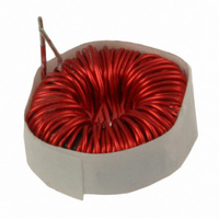
CTX16-18405-R
Description
IND PFC 140UH 3.2A TOROID
Manufacturer
Coiltronics/Div of Cooper/Bussmann
Series
PFCr
Type
Toroidalr
Datasheet
1.CTX16-18405-R.pdf
(3 pages)
Specifications of CTX16-18405-R
Inductance
140µH
Current
3.2A
Dc Resistance (dcr)
190 mOhm Max
Package / Case
Radial
Mounting Type
Through Hole
Applications
General Purpose
Lead Free Status / RoHS Status
Lead free / RoHS Compliant
Tolerance
-
Shielding
-
Q @ Freq
-
Self Resonant Freq
-
Current - Saturation
-
Current - Temperature Rise
-
Other names
513-1658
CTX16-18405-R
Q3794762
CTX16-18405-R
Q3794762


Active PFC functions include:
Buck, boost, flyback and other converter topologies are used in active
PFC circuits.
The DC-DC converter input capacitor also benefits from active PFC.
The capacitor can be sized to filter the high frequency ripple of the
active PFC circuit instead of a much larger capacitor that would be
required to smooth the 50-60Hz input. The regulated input of the DC-
DC converter also demands a lower range of duty cycle from the DC-
DC converter. Other benefits of active PFC include increased “hold-
over-time.” Hold over (brownout protection) benefits from always
starting at the maximum voltage; and because energy in the
capacitor is related to
capacitor in a converter without active PFC.
Boost Inductor
The boost-circuit based PFC topology is the most popular. It is an
economical solution for complying with regulations. The inductance
value is selected based on the desired current ripple in the boost
inductor. The inductance value is expressed as follows.
where:
F F i i g g u u r r e e 3 3 : PFC Boost - Typical application circuit, 3.3 & 5V, 60W combined output power.
The rms boost inductor current is expressed as:
A C
• V pK in (min) is the peak minimum input voltage
• fs is the switching frequency
• Δi is the ripple current
• d(max) is the maximum duty cycle expressed as:
• Active wave shaping of the input current
• Filtering of the high frequency switching
• Feedback sensing of the source current for waveform control
• Feedback control to regulate output voltage
F 1
L =
d(max) =
IL (rms) =
L 2
L 3
V pK in (min) * d(max)
C 1
fs * Δi
1- V pK in (min)
I in (pk)
1
/
2
2
CV
L 1
V o
2
, the capacitor can be much smaller than a
A
C 2
C 3
where V o is the output voltage
M odule
B oost
P F C
L ine
C
out
F 2
F 3
Converter
Converter
D C /D C
D C /D C
3 .3V
5 V
+
+
ou t
ou t
Inductor Selection
Cooper Bussmann Coiltronics
wide variety of PFCs from 100W to 250W. They operate with controllers
from several IC manufacturers to provide PFC supply solutions that utilize
either passive or active PFC applications.
Coiltronics PFC inductors range from 200μH to 1.2mH. The standard input
voltage range is 85V to 385V with different core materials such as ferrite,
powder iron and Kool-Mu™ to provide significant low core loss. The E-core
and toroidal geometries allow using thicker wire to decrease DC resist-
ance and yield higher current capacity. Many vertical or horizontal through-
hole mounting options are available with an operating temperature range of
–20°C to +105°C.
Fuses
AC Input Line Fuse
Product safety standards written by Underwriters Laboratories (UL) and the
International Electrotechnical Commission (IEC) require fuses for primary AC
power protection and secondary protection against any catastrophic failure
within the input filter capacitors, PFC boost module, output electrolytic
capacitors (C out ) or the DC-DC converters. The PFC boost module usually
does not contain overcurrent protection; if a short-circuit is applied across
its output terminals, there is no internal circuit opening device to safely
interrupt the power. Without fuse protection in the AC input line (see
fuse F1 in Figure 3), the boost converter is not protected.
Fusing the DC-DC converter input lines is essential for protection against a
catastrophic DC-DC converter failure (see fuses F2 and F3 in Figure 3).
Protecting the DC-DC Converter
Although the primary input line fuse will eventually activate, DC fuses
positioned right at the input to the DC-DC converters will limit the energy
delivered by the hold-up capacitors (C out ) and will prevent failure to the
PFC boost module.
T T a a b b l l e e 1 1 : : Comparison of passive and active PFC versus no PFC.
Passive switch or
Active
None
Type
PFC
Appearance
With input
voltage,
switch or
fixed input
voltage
With input
voltage,
fixed input
voltage
Without
input voltage
switch
Heaviest
Weight
Normal 90~99.9%
None
®
PFC inductors are available for use with a
50~60%
70~80%
Value
PF
Environment
Impact on
Better
Best
Bad
Expensive
Normal
None
Cost
PFC
Related parts for CTX16-18405-R
Image
Part Number
Description
Manufacturer
Datasheet
Request
R

Part Number:
Description:
TRANSFORMER 1:1.061:1.061
Manufacturer:
Coiltronics/Div of Cooper/Bussmann

Part Number:
Description:
IND PFC W/AUX WDG 1MH 3.1A
Manufacturer:
Coiltronics/Div of Cooper/Bussmann
Datasheet:

Part Number:
Description:
IND PFC 340UH 5.3A TOROID
Manufacturer:
Coiltronics/Div of Cooper/Bussmann
Datasheet:

Part Number:
Description:
IND PFC 200UH 2.0A TOROID
Manufacturer:
Coiltronics/Div of Cooper/Bussmann
Datasheet:
Part Number:
Description:
INDUCT BUCK 400VDC 700UH FERCORE
Manufacturer:
Coiltronics/Div of Cooper/Bussmann

Part Number:
Description:
XFMR FWD 37MH ER28 HORIZ
Manufacturer:
Cooper/Bussmann
Datasheet:

Part Number:
Description:
INDUCTOR SHIELD DUAL 6.8UH SMD
Manufacturer:
Coiltronics/Div of Cooper/Bussmann
Datasheet:

Part Number:
Description:
INDUCTOR TOROID DL 19.6UH DL SMD
Manufacturer:
Coiltronics/Div of Cooper/Bussmann
Datasheet:

Part Number:
Description:
INDUCTOR POWER 33UH 2.4A SMD
Manufacturer:
Coiltronics/Div of Cooper/Bussmann
Datasheet:

Part Number:
Description:
INDUCTOR SHIELD PWR 4.7UH SMD
Manufacturer:
Coiltronics/Div of Cooper/Bussmann
Datasheet:

Part Number:
Description:
INDUCTOR SHIELD PWR 10UH SMD
Manufacturer:
Coiltronics/Div of Cooper/Bussmann
Datasheet: