FWP-10A14F Cooper/Bussmann, FWP-10A14F Datasheet
FWP-10A14F
Manufacturer Part Number
FWP-10A14F
Description
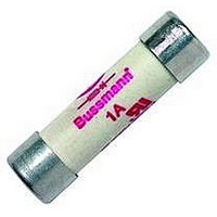
FUSE 10A 660V HS FERRULE
Manufacturer
Cooper/Bussmann
Series
FWPr
Datasheet
1.FWP-20A14F.pdf
(1 pages)
Specifications of FWP-10A14F
Fuse Type
Fast Acting
Voltage - Rated
700VAC, 700VDC
Current
10A
Package / Case
Cylindrical
Size / Dimension
0.563" Dia x 2.000" L (14.30mm x 50.80mm)
Mounting Type
Holder
Melting I²t
22
Voltage Rating Vdc
700V
Voltage Rating Vac
700V
Fuse Current
10A
Blow Characteristic
Fast Acting
Fuse Size Metric
14.3 X 50.8mm
Color
-
Operating Temperature
-
Dc Cold Resistance
-
Lead Free Status / RoHS Status
Lead free / RoHS Compliant
Operating Temperature
-
Color
-
Lead Free Status / Rohs Status
Lead free / RoHS Compliant
Available stocks
Company
Part Number
Manufacturer
Quantity
Price
Company:

Part Number:
FWP-10A14F
Manufacturer:
Cooper Bussmann
Quantity:
5 000
Part Number:
FWP-10A14FA
Manufacturer:
BUSSMANN/巴斯曼
Quantity:
20 000
Ferrule
FWP 660V/700V (IEC/U.L.)
Total Clearing I
The total clearing I
at power factor of 15% are given in the
electrical characteristics. For other volt-
ages, the clearing I
plying by correction factor, K , given as
a function of applied working voltage,
E
Dimensions
Fig. 1: 1-50 Amp Range
Dimension in mm.
1mm = 0.0394∑
Electrical Characteristics
0.3
1.4
1.2
1.0
0.9
0.8
0.7
0.6
0.5
0.4
7-18-01
14 ≈ 51mm
g
CSA Component Acceptance: 5 - 30A.
Interrupting rating 200kA RMS Symmetrical.
Watts loss provided at rated current.
(700 Vdc/Interrupting rating 50kA) U.L. Recognition.
, (RMS).
200 300
(·Ω ¡ §∑)
1)
2)
Size
K
1) 5-30 Amp Range
2) 32-50 Amp Range
(2.000")
50.8
1∑ = 25.4mm
400
SB01191
Electrical Characteristics
RMS-Amps
Current
Rated
2
2
10
15
20
25
30
32
40
50
t at rated voltage and
2
t is found by multi-
1
2
3
4
5
6
t
500
(0.610")
15.5
600
Pre-arc
E
200
1.6
3.6
g
10
26
44
58
68
84
—
—
—
—
—
700
The only controlled copy of this BIF document is the electronic read-only version located on the Bussmann
Network Drive. All other copies of this document are by definition uncontrolled. This bulletin is intended to clearly
present comprehensive product data and provide technical information that will help the end user with design
applications. Bussmann reserves the right, without notice, to change design or construction of any products and
to discontinue or limit distribution of any products. Bussmann also reserves the right to change or update, without
notice, any technical information contained in this bulletin. Once a product has been selected, it should be tested
by the user in all possible applications.
I
2
t (A
(0.563")
2
14.3
Clearing
S)
R
at 660V
1800
180
320
450
600
750
11
22
75
—
—
—
—
—
Arc Voltage
This curve gives the peak arc voltage,
U
during its operation as a function of the
applied working voltage, E
power factor of 15%.
3
1.4
1.2
10
9
8
7
6
5
4
L
, which may appear across the fuse
200 300
3
U
L
Watts
Loss
1.5
5.5
7.6
—
—
—
—
—
4
6
7
9
8
9
400
FWP-1A14F
FWP-2A14F
FWP-3A14F
FWP-4A14F
FWP-5A14F
FWP-6A14F
FWP-10A14F
FWP-15A14F
FWP-20A14F
FWP-25A14F
FWP-30A14F
FWP-32A14F
FWP-40A14F
FWP-50A14F
500
Number
Ordering Information
1-50A
Part
600
g
, (RMS) at a
E
g
700
Carton
Qty.
10
Power Losses
Watts loss at rated current is given in
the electrical characteristics. The curve
allows the calculation of the power
losses at load currents lower than the
rated current . The correction factor, K
is given as a function of the RMS load
current, I
1.0
0.8
0.6
0.5
0.4
0.3
0.2
0.1
Weight
Carton
0.225
(kg)
30 40 50
K
p
b
, in % of the rated current .
Dimensions
Number
Figure
Fig. 1
60
1 kg = 2.2 lbs.
Bussmann
70
80 90 100%
BIF Doc #720025
35785307
Curves
®
BIF #
1 lb = 0.45 kg
I
Page 1 of 1
b
Form No.
p
®
,
Related parts for FWP-10A14F
Image
Part Number
Description
Manufacturer
Datasheet
Request
R

Part Number:
Description:
10A 690V 14X51 INDICATED 14.3 X 50.8MM
Manufacturer:
Cooper/Bussmann
Part Number:
Description:
FUSE 20A 700V HS FERRULE
Manufacturer:
Cooper/Bussmann
Datasheet:
Part Number:
Description:
FUSE 25A 700V HS FERRULE
Manufacturer:
Cooper/Bussmann
Datasheet:

Part Number:
Description:
FUSE 30A 700V FERRULE
Manufacturer:
Cooper/Bussmann
Datasheet:
Part Number:
Description:
Manufacturer:
Cooper/Bussmann
Datasheet: