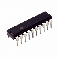
PIC16F677-I/P Microchip Technology, PIC16F677-I/P Datasheet - Page 299

PIC16F677-I/P
Manufacturer Part Number
PIC16F677-I/P
Description
IC PIC MCU FLASH 2KX14 20DIP
Manufacturer
Microchip Technology
Series
PIC® 16Fr
Datasheets
1.PIC16F616T-ISL.pdf
(8 pages)
2.PIC16F690DM-PCTLHS.pdf
(306 pages)
3.PIC16F677-IP.pdf
(2 pages)
4.PIC16F677-IP.pdf
(16 pages)
5.PIC16F677-ISO.pdf
(294 pages)
Specifications of PIC16F677-I/P
Program Memory Type
FLASH
Program Memory Size
3.5KB (2K x 14)
Package / Case
20-DIP (0.300", 7.62mm)
Mfg Application Notes
Intro to Capacitive Sensing Appl Notes Layout and Physical Design Appl Note
Core Processor
PIC
Core Size
8-Bit
Speed
20MHz
Connectivity
I²C, SPI
Peripherals
Brown-out Detect/Reset, POR, WDT
Number Of I /o
18
Eeprom Size
256 x 8
Ram Size
128 x 8
Voltage - Supply (vcc/vdd)
2 V ~ 5.5 V
Data Converters
A/D 12x10b
Oscillator Type
Internal
Operating Temperature
-40°C ~ 85°C
Processor Series
PIC16F
Core
PIC
Data Bus Width
8 bit
Data Ram Size
128 B
Interface Type
SSP
Maximum Clock Frequency
20 MHz
Number Of Programmable I/os
17
Number Of Timers
2
Operating Supply Voltage
2 V to 5.5 V
Maximum Operating Temperature
+ 85 C
Mounting Style
Through Hole
3rd Party Development Tools
52715-96, 52716-328, 52717-734
Development Tools By Supplier
PG164130, DV164035, DV244005, DV164005, PG164120, ICE2000, DM163014, DM164120-4
Minimum Operating Temperature
- 40 C
On-chip Adc
12-ch x 10-bit
Lead Free Status / RoHS Status
Lead free / RoHS Compliant
For Use With
AC162061 - HEADER INTRFC MPLAB ICD2 20PINACICE0203 - MPLABICE 20P 300 MIL ADAPTER
Lead Free Status / Rohs Status
Lead free / RoHS Compliant
Available stocks
Company
Part Number
Manufacturer
Quantity
Price
Company:
Part Number:
PIC16F677-I/P
Manufacturer:
MICROCHIP
Quantity:
2 000
F
Fail-Safe Clock Monitor....................................................... 57
Firmware Instructions........................................................ 217
Flash Program Memory .................................................... 119
Fuses. See Configuration Bits
G
General Purpose Register File............................................ 26
I
I
ID Locations ...................................................................... 215
In-Circuit Serial Programming (ICSP) ............................... 215
Indirect Addressing, INDF and FSR registers ..................... 44
Instruction Format ............................................................. 217
Instruction Set ................................................................... 217
© 2008 Microchip Technology Inc.
2
C Mode
Synchronous Master Mode ............................... 171, 175
Synchronous Slave Mode
Fail-Safe Condition Clearing ....................................... 57
Fail-Safe Detection ..................................................... 57
Fail-Safe Operation..................................................... 57
Reset or Wake-up from Sleep..................................... 57
Addressing ................................................................ 189
Associated Registers ................................................ 196
Master Mode ............................................................. 195
Mode Selection ......................................................... 188
Multi-Master Mode .................................................... 195
Operation .................................................................. 188
Reception.................................................................. 190
Slave Mode
Transmission............................................................. 193
ADDLW ..................................................................... 219
ADDWF..................................................................... 219
ANDLW ..................................................................... 219
ANDWF..................................................................... 219
BCF........................................................................... 219
BSF ........................................................................... 219
BTFSC ...................................................................... 219
BTFSS ...................................................................... 220
CALL ......................................................................... 220
CLRF......................................................................... 220
CLRW ....................................................................... 220
CLRWDT................................................................... 220
COMF ....................................................................... 220
DECF ........................................................................ 220
DECFSZ.................................................................... 221
Baud Rate Error, Calculating ............................ 163
Baud Rates, Asynchronous Modes .................. 164
Formulas ........................................................... 163
High Baud Rate Select (BRGH Bit) .................. 163
Associated Registers
Reception.......................................................... 173
Requirements, Synchronous Receive .............. 249
Requirements, Synchronous Transmission ...... 249
Timing Diagram, Synchronous Receive ........... 249
Timing Diagram, Synchronous Transmission ... 249
Transmission .................................................... 171
Associated Registers
Reception.......................................................... 176
Transmission .................................................... 175
SCL and SDA pins ............................................ 188
Receive..................................................... 174
Transmit.................................................... 172
Receive..................................................... 176
Transmit.................................................... 175
PIC16F631/677/685/687/689/690
INTCON Register................................................................ 38
Inter-Integrated Circuit (I
Internal Oscillator Block
Internal Sampling Switch (R
Internet Address ............................................................... 301
Interrupts .......................................................................... 208
INTOSC Specifications ..................................................... 242
IOCA Register..................................................................... 62
IOCB Register..................................................................... 70
L
Load Conditions................................................................ 240
M
MCLR ............................................................................... 201
Memory Organization ......................................................... 25
Microchip Internet Web Site.............................................. 301
Migrating from other PICmicro Devices ............................ 293
MPLAB ASM30 Assembler, Linker, Librarian ................... 228
MPLAB ICD 2 In-Circuit Debugger ................................... 229
MPLAB ICE 2000 High-Performance Universal
MPLAB Integrated Development Environment Software.. 227
MPLAB PM3 Device Programmer .................................... 229
MPLAB REAL ICE In-Circuit Emulator System ................ 229
MPLINK Object Linker/MPLIB Object Librarian ................ 228
O
OPCODE Field Descriptions............................................. 217
OPTION Register.......................................................... 37, 83
OSCCON Register.............................................................. 48
GOTO ....................................................................... 221
INCF ......................................................................... 221
INCFSZ..................................................................... 221
IORLW ...................................................................... 221
IORWF...................................................................... 221
MOVF ....................................................................... 222
MOVLW .................................................................... 222
MOVWF.................................................................... 222
NOP.......................................................................... 222
RETFIE..................................................................... 223
RETLW ..................................................................... 223
RETURN................................................................... 223
RLF........................................................................... 224
RRF .......................................................................... 224
SLEEP ...................................................................... 224
SUBLW..................................................................... 224
SUBWF..................................................................... 225
SWAPF..................................................................... 225
XORLW .................................................................... 225
XORWF .................................................................... 225
Summary Table ........................................................ 218
INTOSC
ADC .......................................................................... 111
Associated Registers................................................ 210
Context Saving ......................................................... 211
Interrupt-on-Change ................................................... 60
Interrupt-on-change .................................................... 69
PORTA/PORTB Interrupt-on-Change ...................... 209
RA2/INT.................................................................... 208
Timer0 ...................................................................... 209
TMR1.......................................................................... 86
Internal...................................................................... 201
Data ............................................................................ 26
Program...................................................................... 25
In-Circuit Emulator.................................................... 229
Specifications ................................................... 242
2
C). See I
SS
) Impedance ..................... 116
2
C Mode
DS41262E-page 297


