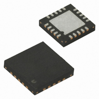
ATTINY24-20MU Atmel, ATTINY24-20MU Datasheet - Page 231

ATTINY24-20MU
Manufacturer Part Number
ATTINY24-20MU
Description
IC MCU AVR 2K FLASH 20MHZ 20-QFN
Manufacturer
Atmel
Series
AVR® ATtinyr
Specifications of ATTINY24-20MU
Core Processor
AVR
Core Size
8-Bit
Speed
20MHz
Connectivity
USI
Peripherals
Brown-out Detect/Reset, POR, PWM, Temp Sensor, WDT
Number Of I /o
12
Program Memory Size
2KB (1K x 16)
Program Memory Type
FLASH
Eeprom Size
128 x 8
Ram Size
128 x 8
Voltage - Supply (vcc/vdd)
2.7 V ~ 5.5 V
Data Converters
A/D 8x10b
Oscillator Type
Internal
Operating Temperature
-40°C ~ 85°C
Package / Case
20-MLF®, QFN
Processor Series
ATTINY2x
Core
AVR8
Data Bus Width
8 bit
Data Ram Size
128 B
Interface Type
USI
Maximum Clock Frequency
20 MHz
Number Of Programmable I/os
12
Number Of Timers
2
Operating Supply Voltage
2.7 V to 5.5 V
Maximum Operating Temperature
+ 85 C
Mounting Style
SMD/SMT
3rd Party Development Tools
EWAVR, EWAVR-BL
Development Tools By Supplier
ATAVRDRAGON, ATSTK500, ATSTK600, ATAVRISP2, ATAVRONEKIT
Minimum Operating Temperature
- 40 C
On-chip Adc
10 bit
For Use With
ATSTK600-DIP40 - STK600 SOCKET/ADAPTER 40-PDIP770-1007 - ISP 4PORT ATMEL AVR MCU SPI/JTAGATAVRISP2 - PROGRAMMER AVR IN SYSTEMATSTK505 - ADAPTER KIT FOR 14PIN AVR MCU
Lead Free Status / RoHS Status
Lead free / RoHS Compliant
Available stocks
Company
Part Number
Manufacturer
Quantity
Price
Part Number:
ATTINY24-20MU
Manufacturer:
AVNET
Quantity:
20 000
Table of Contents
8006K–AVR–10/10
1
2
3
4
5
6
7
Features ..................................................................................................... 1
Pin Configurations ................................................................................... 2
Overview ................................................................................................... 4
About ......................................................................................................... 6
CPU Core .................................................................................................. 7
Memories ................................................................................................ 15
Clock System ......................................................................................... 24
Power Management and Sleep Modes ................................................. 33
1.1
3.1
3.2
3.3
3.4
4.1
4.2
4.3
4.4
4.5
4.6
4.7
5.1
5.2
5.3
5.4
5.5
6.1
6.2
6.3
6.4
6.5
7.1
7.2
Pin Descriptions .................................................................................................2
Resources .........................................................................................................6
Code Examples .................................................................................................6
Data Retention ...................................................................................................6
Disclaimer ..........................................................................................................6
Architectural Overview .......................................................................................7
ALU – Arithmetic Logic Unit ...............................................................................8
Status Register ..................................................................................................8
General Purpose Register File ........................................................................10
Stack Pointer ...................................................................................................11
Instruction Execution Timing ...........................................................................12
Reset and Interrupt Handling ...........................................................................12
In-System Re-programmable Flash Program Memory ....................................15
SRAM Data Memory ........................................................................................15
EEPROM Data Memory ..................................................................................16
I/O Memory ......................................................................................................20
Register Description ........................................................................................20
Clock Subsystems ...........................................................................................24
Clock Sources .................................................................................................25
System Clock Prescaler ..................................................................................30
Clock Output Buffer .........................................................................................30
Register Description ........................................................................................30
Sleep Modes ....................................................................................................33
Software BOD Disable .....................................................................................34
ATtiny24/44/84
i


