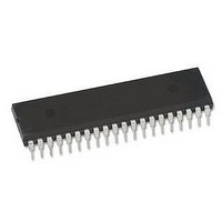
PIC16F1939-I/P Microchip Technology, PIC16F1939-I/P Datasheet - Page 317

PIC16F1939-I/P
Manufacturer Part Number
PIC16F1939-I/P
Description
IC MCU 8BIT FLASH 40-DIP
Manufacturer
Microchip Technology
Series
PIC® XLP™ 16Fr
Datasheets
1.PIC16F722-ISS.pdf
(8 pages)
2.PIC16LF1933-ISS.pdf
(508 pages)
3.PIC16LF1933-ISS.pdf
(46 pages)
4.PIC16F1938-ISS.pdf
(10 pages)
Specifications of PIC16F1939-I/P
Core Size
8-Bit
Program Memory Size
28KB (16K x 14)
Core Processor
PIC
Speed
32MHz
Connectivity
I²C, LIN, SPI, UART/USART
Peripherals
Brown-out Detect/Reset, LCD, POR, PWM, WDT
Number Of I /o
36
Program Memory Type
FLASH
Eeprom Size
256 x 8
Ram Size
1K x 8
Voltage - Supply (vcc/vdd)
1.8 V ~ 5.5 V
Data Converters
A/D 14x10b
Oscillator Type
Internal
Operating Temperature
-40°C ~ 85°C
Package / Case
40-DIP (0.600", 15.24mm)
Controller Family/series
PIC16F
Eeprom Memory Size
256Byte
Ram Memory Size
1024Byte
Cpu Speed
32MHz
No. Of Timers
5
Interface
EUSART, I2C, SPI
Processor Series
PIC16F
Core
PIC
Data Bus Width
8 bit
Data Ram Size
1 KB
Interface Type
EUSART, MI2C, SPI
Maximum Clock Frequency
32 MHz
Number Of Programmable I/os
36
Number Of Timers
5
Maximum Operating Temperature
+ 85 C
Mounting Style
Through Hole
3rd Party Development Tools
52715-96, 52716-328, 52717-734
Development Tools By Supplier
PG164130, DV164035, DV244005, DV164005, PG164120, ICE2000
Minimum Operating Temperature
- 40 C
On-chip Adc
10 bit, 14 Channel
Lead Free Status / RoHS Status
Lead free / RoHS Compliant
Lead Free Status / RoHS Status
Lead free / RoHS Compliant, Lead free / RoHS Compliant
Available stocks
Company
Part Number
Manufacturer
Quantity
Price
Company:
Part Number:
PIC16F1939-I/P
Manufacturer:
IR
Quantity:
5 144
Company:
Part Number:
PIC16F1939-I/P
Manufacturer:
Microchip Technology
Quantity:
1 852
Company:
Part Number:
PIC16F1939-I/PT
Manufacturer:
ON
Quantity:
4 300
Company:
Part Number:
PIC16F1939-I/PT
Manufacturer:
Microchip Technology
Quantity:
10 000
- PIC16F722-ISS PDF datasheet
- PIC16LF1933-ISS PDF datasheet #2
- PIC16LF1933-ISS PDF datasheet #3
- PIC16F1938-ISS PDF datasheet #4
- Current page: 317 of 508
- Download datasheet (5Mb)
25.0
The capacitive sensing module allows for an interaction
with an end user without a mechanical interface. In a
typical application, the capacitive sensing module is
attached to a pad on a Printed Circuit Board (PCB),
which is electrically isolated from the end user. When the
end user places their finger over the PCB pad, a
capacitive load is added, causing a frequency shift in the
capacitive sensing module. The capacitive sensing
module requires software and at least one timer
resource to determine the change in frequency. Key
features of this module include:
• Analog MUX for monitoring multiple inputs
• Capacitive sensing oscillator
• Multiple Power modes
• High power range with variable voltage references
• Multiple timer resources
• Software control
• Operation during Sleep
FIGURE 25-1:
2009 Microchip Technology Inc.
(PIC16F/LF1933/1938/1939 only)
CPS10
CPS11
CPS12
CPS13
CPS14
CPS15
CPS8
CPS9
Note 1:
CPS0
CPS1
CPS2
CPS3
CPS4
CPS5
CPS6
CPS7
CAPACITIVE SENSING
MODULE
(1)
(1)
(1)
(1)
(1)
(1)
(1)
(1)
2:
3:
4:
Reference CPSCON1 register (Register 25-2) for channels implemented on each device.
CPSCH3 is not implemented on PIC16F1933/1936/1938/PIC16LF1933/1936/1938.
If CPSON = 0, disabling capacitive sensing, no channel is selected.
Variable Voltage Reference selection is implemented on PIC16F/LF1934/1936/1937 only.
CAPACITIVE SENSING BLOCK DIAGRAM
CPSON
CPSCH<3:0>
Ref-
(3)
0
1
CPSRM
Capacitive
Oscillator
CPSOSC
Sensing
DAC
Ref+
(2)
CPSRNG<1:0>
(4)
(4)
CPSON
0
1
FVR
Ref.
Int.
(4)
T0CKI
Preliminary
T0XCS
CPSOUT
CPSCLK
0
1
PIC16F193X/LF193X
F
OSC
SYNCC1OUT
SYNCC2OUT
T1GSEL<1:0>
T1CS<1:0>
/4
T1OSC/
F
F
T1G
OSC
T1CKI
OSC
0
1
/4
TMR0CS
Timer0 Module
TMR0
Timer1 Module
Control Logic
Timer1 Gate
EN
TMR1H:TMR1L
Overflow
DS41364D-page 317
TMR0IF
Set
Related parts for PIC16F1939-I/P
Image
Part Number
Description
Manufacturer
Datasheet
Request
R

Part Number:
Description:
IC, 8BIT MCU, PIC16F, 32MHZ, SOIC-18
Manufacturer:
Microchip Technology
Datasheet:

Part Number:
Description:
IC, 8BIT MCU, PIC16F, 32MHZ, SSOP-20
Manufacturer:
Microchip Technology
Datasheet:

Part Number:
Description:
IC, 8BIT MCU, PIC16F, 32MHZ, DIP-18
Manufacturer:
Microchip Technology
Datasheet:

Part Number:
Description:
IC, 8BIT MCU, PIC16F, 32MHZ, QFN-28
Manufacturer:
Microchip Technology
Datasheet:

Part Number:
Description:
IC, 8BIT MCU, PIC16F, 32MHZ, QFN-28
Manufacturer:
Microchip Technology
Datasheet:

Part Number:
Description:
IC, 8BIT MCU, PIC16F, 32MHZ, QFN-28
Manufacturer:
Microchip Technology
Datasheet:

Part Number:
Description:
IC, 8BIT MCU, PIC16F, 32MHZ, SSOP-20
Manufacturer:
Microchip Technology
Datasheet:

Part Number:
Description:
IC, 8BIT MCU, PIC16F, 20MHZ, DIP-40
Manufacturer:
Microchip Technology
Datasheet:

Part Number:
Description:
IC, 8BIT MCU, PIC16F, 32MHZ, QFN-28
Manufacturer:
Microchip Technology
Datasheet:

Part Number:
Description:
IC, 8BIT MCU, PIC16F, 20MHZ, MQFP-44
Manufacturer:
Microchip Technology
Datasheet:

Part Number:
Description:
IC, 8BIT MCU, PIC16F, 20MHZ, QFN-20
Manufacturer:
Microchip Technology
Datasheet:

Part Number:
Description:
IC, 8BIT MCU, PIC16F, 32MHZ, QFN-28
Manufacturer:
Microchip Technology
Datasheet:

Part Number:
Description:
MCU 14KB FLASH 768B RAM 64-TQFP
Manufacturer:
Microchip Technology
Datasheet:

Part Number:
Description:
7 KB Flash, 384 Bytes RAM, 32 MHz Int. Osc, 16 I/0, Enhanced Mid Range Core, Low
Manufacturer:
Microchip Technology

Part Number:
Description:
14KB Flash, 512B RAM, 256B EEPROM, LCD, 1.8-5.5V 40 UQFN 5x5x0.5mm TUBE
Manufacturer:
Microchip Technology
Datasheet:


