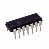
PIC16F506-I/P Microchip Technology, PIC16F506-I/P Datasheet - Page 7

PIC16F506-I/P
Manufacturer Part Number
PIC16F506-I/P
Description
IC PIC MCU FLASH 1KX14 14DIP
Manufacturer
Microchip Technology
Series
PIC® 16Fr
Datasheets
1.PIC12F510-ISN.pdf
(124 pages)
2.PIC16F506-ISL.pdf
(12 pages)
3.PIC16F506-ISL.pdf
(8 pages)
4.PIC16F506-ISL.pdf
(22 pages)
5.PIC16F506-IP.pdf
(114 pages)
Specifications of PIC16F506-I/P
Program Memory Type
FLASH
Program Memory Size
1.5KB (1K x 12)
Package / Case
14-DIP (0.300", 7.62mm)
Core Processor
PIC
Core Size
8-Bit
Speed
20MHz
Peripherals
POR, WDT
Number Of I /o
11
Ram Size
67 x 8
Voltage - Supply (vcc/vdd)
2 V ~ 5.5 V
Data Converters
A/D 4x8b
Oscillator Type
Internal
Operating Temperature
-40°C ~ 85°C
Processor Series
PIC16F
Core
PIC
Data Bus Width
8 bit
Data Ram Size
67 B
Maximum Clock Frequency
20 MHz
Number Of Programmable I/os
12
Number Of Timers
1
Maximum Operating Temperature
+ 85 C
Mounting Style
Through Hole
3rd Party Development Tools
52715-96, 52716-328, 52717-734
Development Tools By Supplier
PG164130, DV164035, DV244005, DV164005, PG164120, ICE2000
Minimum Operating Temperature
- 40 C
On-chip Adc
3-ch x 8-bit
Lead Free Status / RoHS Status
Lead free / RoHS Compliant
For Use With
AC162070 - HEADER INTRFC MPLAB ICD2 8/14P
Eeprom Size
-
Connectivity
-
Lead Free Status / Rohs Status
Lead free / RoHS Compliant
Available stocks
Company
Part Number
Manufacturer
Quantity
Price
Part Number:
PIC16F506-I/P
Manufacturer:
MICROCHIP/微芯
Quantity:
20 000
3.1.2.5
The End Programming command terminates the
program process. A delay of T
required before the next command to allow the internal
programming voltage to discharge (see Figure 3-6).
FIGURE 3-6:
3.1.2.6
After this command is performed, the entire program
memory and Configuration Word is erased.
To perform a Bulk Erase of the program memory and
configuration fuses, the following sequence must be
performed (see Figure 3-12).
1.
2.
3.
4.
5.
6.
2010 Microchip Technology Inc.
Note:
Note:
Read and save 0x3FF oscillator Calibration bits
and 0x404 backup OSCCAL bits into computer/
programmer temporary memory.
Enter Program/Verify mode. PC is set to
Configuration Word address.
Perform a Bulk Erase Program Memory
command.
Wait T
Restore OSCCAL bits.
Restore backup OCCAL bits.
ICSPCLK
ICSPDAT
ERA
A fully erased part will read ‘1’s in every
program memory location.
The oscillator Calibration bits are erased if
a Bulk Erase is invoked. They must be
read and saved prior to erasing the device
and restored during the programming
operation. Oscillator Calibration bits are
stored at the Reset vector as the operand
of a MOVLW instruction.
End Programming
Bulk Erase Program Memory
to complete Bulk Erase.
END PROGRAMMING (EXTERNALLY TIMED)
DIS
1
0
(see Table 6-1) is
2
1
T
3
1
SET
1
4
1
To perform a full device Bulk Erase of the program
memory, configuration fuses, user IDs and backup
OSCCAL, the following sequence must be performed
(see Figure 3-13).
1.
2.
3.
4.
5.
6.
7.
T
HLD
Read and save 0x3FF oscillator Calibration bits
and 0x404 backup OSCCAL bits into computer/
programmer temporary memory.
Enter Program/Verify mode.
Increment PC to 0x400 (first user ID location).
Perform a Bulk Erase command.
Wait T
Restore OSCCAL bits.
Restore backup OSCCAL bits.
5
x
1
ERA
6
x
to complete Bulk Erase.
T
DIS
1
Next Command
PIC16F506
2
DS41258C-page 7


