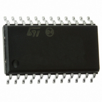
ST72F63BE2M1 STMicroelectronics, ST72F63BE2M1 Datasheet - Page 35

ST72F63BE2M1
Manufacturer Part Number
ST72F63BE2M1
Description
MCU 8BIT LS USB 8KB FLASH 24SOIC
Manufacturer
STMicroelectronics
Series
ST7r
Datasheet
1.ST72F63BD6U1TR.pdf
(186 pages)
Specifications of ST72F63BE2M1
Core Processor
ST7
Core Size
8-Bit
Speed
8MHz
Connectivity
I²C, SCI, USB
Peripherals
DMA, LVD, POR, PWM, WDT
Number Of I /o
14
Program Memory Size
8KB (8K x 8)
Program Memory Type
FLASH
Ram Size
1K x 8
Voltage - Supply (vcc/vdd)
4 V ~ 5.5 V
Oscillator Type
Internal
Operating Temperature
0°C ~ 70°C
Package / Case
24-SOIC (7.5mm Width)
Data Converters
A/D 12x10b
Processor Series
ST72F6x
Core
ST7
Data Bus Width
8 bit
Data Ram Size
384 B
Interface Type
I2C, SCI
Maximum Clock Frequency
8 MHz
Number Of Programmable I/os
14
Number Of Timers
1
Maximum Operating Temperature
+ 70 C
Mounting Style
SMD/SMT
Development Tools By Supplier
ST7MDTU3-EPB/US, ST7MDTULS-EVAL, ST72F63B-SK/RAIS, ST7MDTU3-EMU3, STX-RLINK
Minimum Operating Temperature
0 C
For Use With
497-8209 - BOARD EVAL USB STUSB02E/ST72F63B497-8208 - BOARD EVAL USB STUSB03E/ST72F63B497-5521 - EVAL BOARD LOW SPEED USB497-5046 - KIT TOOL FOR ST7/UPSD/STR7 MCU
Lead Free Status / RoHS Status
Lead free / RoHS Compliant
Eeprom Size
-
Lead Free Status / Rohs Status
Details
Other names
497-5624-5
Available stocks
Company
Part Number
Manufacturer
Quantity
Price
ST7263Bxx
6.2
6.2.1
6.2.2
Clock system
General description
The MCU accepts either a crystal or ceramic resonator, or an external clock signal to drive
the internal oscillator. The internal clock (f
frequency (f
clock used). The internal clock is further divided by 2 by setting the SMS bit in the
miscellaneous register.
Using the OSC24/12 bit in the option byte, a 12 MHz or a 24 MHz external clock can be
used to provide an internal frequency of either 2, 4 or 8 MHz while maintaining a 6 MHz for
the USB (refer to
The internal clock signal (f
signal consists of a square wave with a duty cycle of 50%.
The internal oscillator is designed to operate with an AT-cut parallel resonant quartz or
ceramic resonator in the frequency range specified for f
recommended when using a crystal, and
crystal and associated components should be mounted as close as possible to the input
pins in order to minimize output distortion and start-up stabilization time.
Table 8.
1. R
External clock
An external clock may be applied to the OSCIN input with the OSCOUT pin not connected,
as shown on
input. The equivalent specification of the external clock source should be used instead of
t
Figure 16. External clock source connections
OXOV
SMAX
(see
C
R
C
OSCOUT
SMAX
is the equivalent serial resistor of the crystal (see crystal specification).
OSCIN
R
Table 62: Control timing
P
OSC
Recommended Values for 24 MHz crystal resonator
Figure
(1)
), which is divided by 3 (and by 2 or 4 for USB, depending on the external
Figure
16. The t
18).
Recommended capacitance and resistance
CPU
OXOV
) is also routed to the on-chip peripherals. The CPU clock
1-10 MΩ
Doc ID 7516 Rev 8
56pF
56pF
20 Ω
specifications do not apply when using an external clock
EXTERNAL
characteristics).
CLOCK
OSCIN
Table 8
CPU
) is derived from the external oscillator
OSCOUT
NC
lists the recommended capacitance. The
1-10 MΩ
osc
47pF
47pF
25 Ω
. The circuit shown in
Reset and clock management
1-10 MΩ
22pF
22pF
70 Ω
Figure 17
35/186
is


