COP8SGR744V8/NOPB National Semiconductor, COP8SGR744V8/NOPB Datasheet
COP8SGR744V8/NOPB
Specifications of COP8SGR744V8/NOPB
COP8SGR744V8
Available stocks


Related parts for COP8SGR744V8/NOPB

COP8SGR744V8/NOPB Summary of contents
Page 1
... Versatile easy to use instruction set n 0.67 µs instruction cycle time COP8 ™ trademark of National Semiconductor Corporation. © 2001 National Semiconductor Corporation Erasable windowed versions (Q3) are available for use with a range of COP8 software and hardware development tools. Family features include an 8-bit memory mapped architec- ture, 15 MHz CKI with 0.67 µ ...
Page 2
Peripheral Features (Continued) n Idle Timer (T0) n MICROWIRE/PLUS Serial Interface (SPI Compatible) n Full Duplex USART n Two Analog Comparators I/O Features n Software selectable I/O options (TRI-STATE Output,Push-Pull Output, Weak Pull-Up Input, and High Impedance Input) n Schmitt ...
Page 3
Device Description 1.1 ARCHITECTURE The COP8 family is based on a modified Harvard architec- ture, which allows data tables to be accessed directly from program memory. This is very important with modern microcontroller-based applications, since program memory is usually ...
Page 4
Connection Diagrams 10131704 Top View Order Number COP8SGXY28M8 See NS Package Number M28B Order Number COP8SGXY28N8 See NS Package Number N28B Order Number COP8SGR728Q3 See NS Package Number D28JQ Top View Order Number COP8SGXY44V8 See NS Package Number V44A Order ...
Page 5
Pinouts for 28 -, 40- and 44-Pin Packages Port Type Alt. Fun L0 I/O MIWU L1 I/O MIWU or CKX L2 I/O MIWU or TDX L3 I/O MIWU or RDX L4 I/O MIWU or T2A L5 I/O MIWU or T2B ...
Page 6
Ordering Information www.national.com FIGURE 2. Part Numbering Scheme 6 10131708 ...
Page 7
... Electrical Characteristics Absolute Maximum Ratings If Military/Aerospace specified devices are required, please contact the National Semiconductor Sales Office/ Distributors for availability and specifications. Supply Voltage ( Voltage at Any Pin −0. Total Current into V CC Pin (Source) DC Electrical Characteristics −40˚C T +85˚C unless otherwise specified. ...
Page 8
DC Electrical Characteristics −40˚C T +85˚C unless otherwise specified. A Parameter Output Current Levels D Outputs Source Sink All Others Source (Weak Pull-Up Mode) Source (Push-Pull Mode) Sink (Push-Pull Mode) TRI-STATE Leakage Allowable Sink Current per Pin (Note 9) D ...
Page 9
... ESD transients. Note 8: National Semiconductor uses the High Temperature Storage Life (HTSL) test to evaluate the data retention capabilities of the EPROM memory cells used in our OTP microcontrollers. Qualification devices have been stressed at 150˚C for 1000 hours. Under these conditions, our EPROM cells exhibit data retention capabilities in excess of 29 years. This is based on an activation energy of 0.7eV derated to 55˚ ...
Page 10
... Absolute Maximum Ratings If Military/Aerospace specified devices are required, please contact the National Semiconductor Sales Office/ Distributors for availability and specifications. Supply Voltage ( Voltage at Any Pin −0. Total Current into V CC Pin (Source) Total Current out of GND Pin (Sink) DC Electrical Characteristics −40˚C T +125˚ ...
Page 11
DC Electrical Characteristics −40˚C T +125˚C unless otherwise specified. A Parameter Maximum Input Current without Latchup (Note 7) RAM Retention Voltage Rise Time from EPROM Data Retenton (Note 8),(Note 9) Input Capacitance Load ...
Page 12
AC Electrical Characteristics −40˚C T +125˚C unless otherwise specified. A Parameter Instruction Cycle Time ( Crystal/Resonator, External R/C Oscillator (Internal) Frequency Variation (Note 9) External CKI Clock Duty Cycle (Note 9) Rise Time (Note 9) Fall Time (Note ...
Page 13
Typical Performance Characteristics T = 25˚C (unless otherwise specified) A 10131749 10131751 13 10131750 10131752 www.national.com ...
Page 14
Pin Descriptions The COP8SGx I/O structure enables designers to reconfig- ure the microcontroller’s I/O functions with a single instruc- tion. Each individual I/O pin can be independently configured as output pin low, output high, input with high impedance or ...
Page 15
Pin Descriptions (Continued) Note: For compatibility with existing software written for COP888xG devices and with existing Mask ROM devices, a read of the Port I input pins (address xxD7) will return the same data as reading the Port F ...
Page 16
Functional Description The architecture of the devices are a modified Harvard ar- chitecture. With the Harvard architecture, the program memory ROM is separated from the data store memory (RAM). Both ROM and RAM have their own separate ad- dressing ...
Page 17
Functional Description The instructions that utilize the stack pointer (SP) always reference the stack as part of the base segment (Segment 0), regardless of the contents of the S register. The S register is not changed by these instructions. ...
Page 18
Functional Description programmed to 0 for all other applications Enable full port F capability. Bit HALT mode disabled HALT mode enabled. 5.6 USER STORAGE SPACE IN EPROM The ECON register is outside ...
Page 19
Functional Description The device comes out of reset with both the WATCH- DOG logic and the Clock Monitor detector armed, with the WATCHDOG service window bits set and the Clock Monitor bit set. The WATCHDOG and Clock Monitor circuits ...
Page 20
Functional Description 5.10 OSCILLATOR CIRCUITS There are four clock oscillator options available: Crystal Oscillator with or without on-chip bias resistor, R/C Oscillator with on-chip resistor and capacitor, and External Oscillator. The oscillator feature is selected by programming the ECON ...
Page 21
Functional Description 10131719 FIGURE 13. External Oscillator For operation at lower than maximum R/C oscillator frequency. 10131721 For operation at maximum R/C oscillator frequency. FIGURE 14. R/C Oscillator 5.11 CONTROL REGISTERS CNTRL Register (Address X'00EE) T1C3 T1C2 T1C1 T1C0 ...
Page 22
Functional Description T3CNTRL Register (Address X'00B6) T3C3 T3C2 T3C1 T3C0 T3PNDA Bit 7 The T3CNTRL control register contains the following bits: T3C3 Timer T3 mode control bit T3C2 Timer T3 mode control bit T3C1 Timer T3 mode control bit ...
Page 23
Timers (Continued) FIGURE 15. Timer in PWM Mode In this mode the input pin TxB can be used as an indepen- dent positive edge sensitive interrupt input if the TxENB control flag is set. The occurrence of a positive ...
Page 24
Timers (Continued) 6.3 TIMER CONTROL FLAGS The control bits and their functions are summarized below. TxC3 Timer mode control TxC2 Timer mode control TxC1 Timer mode control TxC0 Timer Start/Stop control in Modes 1 and 2 (Pro- cessor Independent ...
Page 25
Power Saving Features Today, the proliferation of battery-operated based applica- tions has placed new demands on designers to drive power consumption down. Battery-operated systems are not the only type of applications demanding low power. The power budget constraints are ...
Page 26
Power Saving Features 7.2 IDLE MODE The device is placed in the IDLE mode by writing a “1” to the IDLE flag (G6 data bit). In this mode, all activities, except the associated on-board oscillator circuitry and the IDLE ...
Page 27
Power Saving Features 7.3 MULTI-INPUT WAKEUP The Multi-Input Wakeup feature is used to return (wakeup) the device from either the HALT or IDLE modes. Alternately Multi-Input Wakeup/Interrupt feature may also be used to generate edge selectable ...
Page 28
USART Each device contains a full-duplex software programmable USART. The USART ( Figure 21 ) consists of a transmit shift register, a receive shift register and seven addressable reg- isters, as follows: a transmit buffer register (TBUF), a re- ...
Page 29
USART (Continued) PEN: This bit enables/disables Parity (7- and 8-bit modes only). Read/Write, cleared on reset. PEN = 0 Parity disabled. PEN = 1 Parity enabled. PSEL1, PSEL0: Parity select bits. Read/Write, cleared on reset. PSEL1 = 0, PSEL0 ...
Page 30
USART (Continued) 8.3 Associated I/O Pins Data is transmitted on the TDX pin and received on the RDX pin. TDX is the alternate function assigned to Port L pin L2 selected by setting ETDX (in the ENUI ...
Page 31
USART (Continued) 8.6 USART INTERRUPTS The USART is capable of generating interrupts. Interrupts are generated on Receive Buffer Full and Transmit Buffer Empty. Both interrupts have individual interrupt vectors. Two bytes of program memory space are reserved for each ...
Page 32
USART (Continued) rates may be created by using appropriate divisors. The 16x clock is then divided provide the rate for the serial shift registers of the transmitter and receiver. TABLE 4. Baud Rate Divisors (1.8432 MHz ...
Page 33
USART (Continued example, considering Asynchronous Mode and a CKI clock of 4.608 MHz, the prescaler factor selected is: 4.608/1.8432 = 2.5 The 2.5 entry is available in Table 5 . The 1.8432 MHz prescaler output is then ...
Page 34
Comparators (Continued) F1 Comparator1 negative input A Comparator Select Register (CMPSL) is used to enable the comparators, read the outputs of the comparators inter- nally, and enable the outputs of the comparators to the pins. Two control bits (enable ...
Page 35
Interrupts (Continued) 10.2 MASKABLE INTERRUPTS All interrupts other than the Software Trap are maskable. Each maskable interrupt has an associated enable bit and pending flag bit. The pending bit is set to 1 when the interrupt condition occurs. The ...
Page 36
Interrupts (Continued) ample, if the Software Trap routine is located at 0310 Hex, then the vector location 0yFE and -0yFF should contain the data 03 and 10 Hex, respectively. When a Software Trap interrupt occurs and the VIS instruction ...
Page 37
Interrupts (Continued) 10.3.1 VIS Execution When the VIS instruction is executed it activates the arbitra- tion logic. The arbitration logic generates an even number between E0 and FE (E0, E2, E4, E6 etc...) depending on which active interrupt has ...
Page 38
Interrupts (Continued) www.national.com FIGURE 27. VIS Flowchart 38 10131730 ...
Page 39
Interrupts (Continued) Programming Example: External Interrupt PSW =00EF CNTRL =00EE RBIT 0,PORTGC RBIT 0,PORTGD SBIT IEDG, CNTRL SBIT EXEN, PSW SBIT GIE, PSW WAIT: JP WAIT . . . .=0FF VIS . . . .=01FA .ADDRW SERVICE . . ...
Page 40
Interrupts (Continued) 10.4 NON-MASKABLE INTERRUPT 10.4.1 Pending Flag There is a pending flag bit associated with the non-maskable interrupt, called STPND. This pending flag is not memory- mapped and cannot be accessed directly by the software. The pending flag ...
Page 41
WATCHDOG/Clock Monitor Each device contains a user selectable WATCHDOG and clock monitor. The following section is applicable only if WATCHDOG feature has been selected in the ECON regis- ter. The WATCHDOG is designed to detect the user program getting ...
Page 42
WATCHDOG/Clock Monitor Key Data Match Don’t Care Mismatch Don’t Care Don’t Care Don’t Care 11.3 WATCHDOG AND CLOCK MONITOR SUMMARY The following salient points regarding the WATCHDOG and CLOCK MONITOR should be noted: • Both the WATCHDOG and CLOCK ...
Page 43
MICROWIRE/PLUS arrangement with the internal clock source is called the Master mode of operation. Similarly, operating the MICROWIRE/PLUS arrangement with an external shift clock is called the Slave mode of operation. The CNTRL register is used to configure and ...
Page 44
MICROWIRE/PLUS 12.1.2 MICROWIRE/PLUS Slave Mode Operation In the MICROWIRE/PLUS Slave mode of operation the SK clock is generated by an external source. Setting the MSEL bit in the CNTRL register enables the SO and SK functions onto the G ...
Page 45
MICROWIRE/PLUS FIGURE 30. MICROWIRE/PLUS SPI Mode Interface Timing, Alternate SK Mode, SK Idle Phase being Low FIGURE 31. MICROWIRE/PLUS SPI Mode Interface Timing, Normal SK Mode, SK Idle Phase being High FIGURE 32. MICROWIRE/PLUS SPI Mode Interface Timing, Alternate ...
Page 46
Memory Map All RAM, ports and registers (except A and PC) are mapped into data memory address space. Address Contents S/ADD REG 0000 to 006F On-Chip RAM bytes (112 bytes) 0070 to 007F Unused RAM Address Space (Reads As ...
Page 47
Instruction Set 14.1 INTRODUCTION This section defines the instruction set of the COP8 Family members. It contains information about the instruction set features, addressing modes and types. 14.2 INSTRUCTION FEATURES The strength of the instruction set is based on ...
Page 48
Instruction Set (Continued) Example: Load Accumulator Immediate Reg/Data Contents Memory Before Accumulator XX Hex Immediate Short. This is a special case of an immediate instruction. In the “Load B immediate” instruction, the 4-bit immediate value ...
Page 49
Instruction Set (Continued) Reg/ Contents Memory Before Location 32 Hex 0126 Hex The VIS instruction is a special case of the Indirect Transfer of Control addressing mode, where the double-byte vector associated with the interrupt is transferred from adjacent ...
Page 50
Instruction Set (Continued) 14.5 REGISTER AND SYMBOL DEFINITION The following abbreviations represent the nomenclature used in the instruction description and the COP8 cross-assembler. Registers A 8-Bit Accumulator Register B 8-Bit Address Register X 8-Bit Address Register SP 8-Bit Stack ...
Page 51
Instruction Set (Continued) INC A INCrement A DEC A DECrement A LAID Load A InDirect from ROM DCOR A Decimal CORrect A RRC A Rotate A Right thru C RLC A Rotate A Left thru C SWAP A SWAP ...
Page 52
Instruction Set (Continued) 14.7 INSTRUCTION EXECUTION TIME Most instructions are single byte (with immediate addressing mode instructions taking two bytes). Most single byte instructions take one cycle time to execute. Skipped instructions require x number of cycles to be ...
Page 53
Nibble Lower 53 www.national.com ...
Page 54
www.national.com 54 ...
Page 55
Mask Options See Section 5.5 ECON (CONFIGURATION) REGISTER. 16.0 COP8 Tools Overview National is engaged with an international community of in- dependent 3rd party vendors who provide hardware and software development tool support. Through National’s inter- action and guidance, ...
Page 56
COP8 Tools Overview 16.2 TOOLS ORDERING NUMBERS FOR THE COP8SGx FAMILY DEVICES The COP8-IM/400 ICE can be used for emulation with the limitation of 10 MHz emulation speed maximum. For full speed COP8SGx emulation, use the 15 MHz COP8-DM-SG ...
Page 57
COP8 Tools Overview 16.3 WHERE TO GET TOOLS Tools can be ordered directly from National, National’s e-store, a National Distributor, or from the tool vendor the vendor’s web site for current listings of distributors. Vendor Home Office ...
Page 58
Physical Dimensions www.national.com inches (millimeters) unless otherwise noted Chip Scale Package CSP Order Number COP8SGR7HLQ8 NS Package Number LQA44A Molded SO Wide Body Package (WM) Order Number COP8SGx528Mx, NS Package Number M28B 58 ...
Page 59
Physical Dimensions inches (millimeters) unless otherwise noted (Continued) Molded Dual-In-Line Package (N) Order Number COP8SGx728Nx NS Package Number N28B Molded Dual-In-Line Package (N) Order Number COP8SGx540Nx NS Package Number N40A 59 www.national.com ...
Page 60
Physical Dimensions www.national.com inches (millimeters) unless otherwise noted (Continued) 44-Lead EPROM Leaded Chip Carrier (EL) Order Number COP8SGR744J3 NS Package Number EL44C 60 ...
Page 61
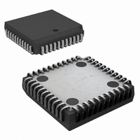
Physical Dimensions inches (millimeters) unless otherwise noted (Continued) Molded Dual-In-Line Package (N) Order Number COP8SGx544Vx NS Package Number V44A 61 www.national.com ...
Page 62
... NATIONAL’S PRODUCTS ARE NOT AUTHORIZED FOR USE AS CRITICAL COMPONENTS IN LIFE SUPPORT DEVICES OR SYSTEMS WITHOUT THE EXPRESS WRITTEN APPROVAL OF THE PRESIDENT AND GENERAL COUNSEL OF NATIONAL SEMICONDUCTOR CORPORATION. As used herein: 1. Life support devices or systems are devices or systems which, (a) are intended for surgical implant ...