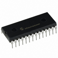
PIC16F57-I/P Microchip Technology, PIC16F57-I/P Datasheet - Page 17

PIC16F57-I/P
Manufacturer Part Number
PIC16F57-I/P
Description
IC MCU FLASH 2KX12 28DIP
Manufacturer
Microchip Technology
Series
PIC® 16Fr
Datasheets
1.PIC16F54-ISS.pdf
(88 pages)
2.PIC16F57-ISS.pdf
(16 pages)
3.PIC16F57-ISO.pdf
(86 pages)
Specifications of PIC16F57-I/P
Program Memory Type
FLASH
Program Memory Size
3KB (2K x 12)
Package / Case
28-DIP (0.600", 15.24mm)
Core Processor
PIC
Core Size
8-Bit
Speed
20MHz
Peripherals
POR, WDT
Number Of I /o
20
Ram Size
72 x 8
Voltage - Supply (vcc/vdd)
2 V ~ 5.5 V
Oscillator Type
External
Operating Temperature
-40°C ~ 85°C
Processor Series
PIC16F
Core
PIC
Data Bus Width
8 bit
Data Ram Size
72 B
Maximum Clock Frequency
20 MHz
Number Of Programmable I/os
20
Number Of Timers
1
Operating Supply Voltage
2 V to 5.5 V
Maximum Operating Temperature
+ 85 C
Mounting Style
Through Hole
3rd Party Development Tools
52715-96, 52716-328, 52717-734
Development Tools By Supplier
DV164120, DV164101, ICE2000
Minimum Operating Temperature
- 40 C
Data Rom Size
2 K
Height
3.3 mm
Length
34.67 mm
Supply Voltage (max)
5.5 V
Supply Voltage (min)
2 V
Width
7.24 mm
Lead Free Status / RoHS Status
Lead free / RoHS Compliant
For Use With
XLT28XP - SOCKET TRANSITION ICE 28DIPAC164001 - MODULE SKT PROMATEII 18/28DIP
Eeprom Size
-
Data Converters
-
Connectivity
-
Lead Free Status / Rohs Status
Lead free / RoHS Compliant
Available stocks
Company
Part Number
Manufacturer
Quantity
Price
Company:
Part Number:
PIC16F57-I/P
Manufacturer:
Microchip Technology
Quantity:
26 657
Part Number:
PIC16F57-I/P
Manufacturer:
MICROCHIP/微芯
Quantity:
20 000
3.2.2
The Special Function Registers (FSR) are registers
used by the CPU and peripheral functions to control the
operation of the device (Table 3-1).
The Special Function Registers can be classified into
two sets. The Special Function Registers associated
with the “core” functions are described in this section.
TABLE 3-1:
2004 Microchip Technology Inc.
N/A
N/A
00h
01h
02h
03h
04h
05h
06h
07h
Legend:
Note 1:
Address
(1)
(4)
(2)
2:
3:
4:
Shaded cells = unimplemented or unused, – = unimplemented, read as ‘0’ (if applicable), x = unknown, u = unchanged
The upper byte of the Program Counter is not directly accessible. See Section 3.5 “Program Counter” for an
explanation of how to access these bits.
File address 07h is a General Purpose Register on the PIC16F54.
These values are valid for PIC16F57. For the PIC16F54, the value on Reset is ‘111x xxxx’ and for MCLR and WDT
Reset, the value is ‘111u uuuu’.
Unimplemented bits are read as ‘0’s.
SPECIAL FUNCTION REGISTERS
TRIS
OPTION
INDF
TMR0
PCL
STATUS
FSR
PORTA
PORTB
PORTC
Name
SPECIAL FUNCTION REGISTER SUMMARY
I/O Control Registers (TRISA, TRISB, TRISC)
Contains control bits to configure Timer0 and Timer0/WDT prescaler
Uses Contents of FSR to Address Data Memory (not a physical register)
Timer0 Module Register
Low order 8 bits of PC
Indirect Data Memory Address Pointer
Bit 7
RB7
RC7
PA2
—
Bit 6
RC6
RB6
PA1
—
Bit 5
RC5
PA0
RB5
—
Bit 4
RB4
RC4
TO
—
Preliminary
Bit 3
RC3
RA3
RB3
PD
Those related to the operation of the peripheral
features are described in the section for each
peripheral feature.
Bit 2
RC2
RA2
RB2
Z
Bit 1
RA1
RB1
RC1
DC
Bit 0
RA0
RB0
RC0
C
Power-on Reset
1xxx xxxx
1111 1111
--11 1111
xxxx xxxx
xxxx xxxx
1111 1111
0001 1xxx
---- xxxx
xxxx xxxx
xxxx xxxx
Value on
PIC16F5X
DS41213B-page 15
(1)
Details on
Page
29
17
19
32
18
16
19
29
29
29


