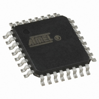
AT89LP428-20MH Atmel, AT89LP428-20MH Datasheet - Page 67

AT89LP428-20MH
Manufacturer Part Number
AT89LP428-20MH
Description
MCU 8051 4K FLASH SPI 32VQFN
Manufacturer
Atmel
Series
89LPr
Datasheet
1.AT89LP428-20AU.pdf
(149 pages)
Specifications of AT89LP428-20MH
Core Processor
8051
Core Size
8-Bit
Speed
20MHz
Connectivity
SPI, UART/USART
Peripherals
Brown-out Detect/Reset, POR, PWM, WDT
Number Of I /o
30
Program Memory Size
4KB (4K x 8)
Program Memory Type
FLASH
Eeprom Size
512 x 8
Ram Size
768 x 8
Voltage - Supply (vcc/vdd)
2.4 V ~ 5.5 V
Oscillator Type
Internal
Operating Temperature
-40°C ~ 85°C
Package / Case
32-TQFP
Processor Series
AT89x
Core
8051
3rd Party Development Tools
PK51, CA51, A51, ULINK2
Development Tools By Supplier
AT89ISP
Lead Free Status / RoHS Status
Lead free / RoHS Compliant
Data Converters
-
Lead Free Status / Rohs Status
Details
- Current page: 67 of 149
- Download datasheet (5Mb)
13.3.1
13.3.1.1
13.3.1.2
3654A–MICRO–8/09
Waveform Generation
Normal Mode
Clear-Timer-on-Compare Mode
Each CCA channel has an associated external compare output pin: CCA (P2.0), CCB (P2.1),
CCC (P2.2) and CCD (P2.3). The CxM
compare event occurs. The output pin may be set to 1, cleared to 0 or toggled. Output actions
take place even if the interrupt is disabled; however, the associated I/O pin must be set to the
desired output mode before the compare event occurs. The state of the compare outputs are ini-
tialized to 1 by reset.
Multiple compare events per channel can occur within a single time period, provided that the
software has time to update the compare value before the timer reaches the next compare point.
In this case other interrupts should be disabled or the CCA interrupt given a higher priority in
order to ensure that the interrupt is serviced in time.
A wide range of waveform generation configurations are possible using the various operating
modes of Timer 2 and the CCA. Some example configurations are detailed below. Pulse width
modulation is a special case of output compare. See
for more details of PWM operation.
The simplest waveform mode is when CP/RL2 = 0 and T2CM1-0 = 01B. In this mode the fre-
quency of the output is determined by the TOP value stored in RCAP2L and RCAP2H and
output edges occur at fractions of the timer period.
two waveforms of the same frequency but different phase by using the toggle on match action.
More complex waveforms are achieved by changing the TOP value and the compare values
more frequently.
Figure 13-4. Normal Mode Waveform Example
Clear-Timer-on-Compare (CTC) mode occurs when the CTCx bit of a compare channel is set to
one. CTC mode works best when Timer 2 is in capture mode (CP/RL2 = 1) to allow the full range
of compare values. In CTC mode, the compare value defines the interval between output events
because the timer is cleared after every compare match.
form using the toggle on match action in CTC mode.
{RCAP2H,RCA2L}
{CCAH,CCAL}
{CCBH,CCBL}
CCA
CCB
2-0
CP/RL2 = 0, T2CM
bits in CCCx determine what action is taken when a
Figure 13-4
“Pulse Width Modulation Mode” on page 68
1-0
Figure 13-5
= 01B, DCEN = 0
shows an example of outputting
AT89LP428/828
shows an example wave-
67
Related parts for AT89LP428-20MH
Image
Part Number
Description
Manufacturer
Datasheet
Request
R

Part Number:
Description:
Manufacturer:
Atmel Corporation
Datasheet:

Part Number:
Description:
8-bit Microcontroller with 4K/8K Bytes In-System Programmable Flash
Manufacturer:
ATMEL [ATMEL Corporation]
Datasheet:

Part Number:
Description:
MCU 8051 4K FLASH SPI 32TQFP
Manufacturer:
Atmel
Datasheet:

Part Number:
Description:
MCU 8051 4K FLASH SPI 28PDIP
Manufacturer:
Atmel
Datasheet:

Part Number:
Description:
MCU 8051 4K FLASH SPI 32PLCC
Manufacturer:
Atmel
Datasheet:

Part Number:
Description:
8-bit Microcontroller With 4k/8k Bytes In-system Programmable Flash
Manufacturer:
ATMEL Corporation
Datasheet:

Part Number:
Description:
DEV KIT FOR AVR/AVR32
Manufacturer:
Atmel
Datasheet:

Part Number:
Description:
INTERVAL AND WIPE/WASH WIPER CONTROL IC WITH DELAY
Manufacturer:
ATMEL Corporation
Datasheet:

Part Number:
Description:
Low-Voltage Voice-Switched IC for Hands-Free Operation
Manufacturer:
ATMEL Corporation
Datasheet:

Part Number:
Description:
MONOLITHIC INTEGRATED FEATUREPHONE CIRCUIT
Manufacturer:
ATMEL Corporation
Datasheet:

Part Number:
Description:
AM-FM Receiver IC U4255BM-M
Manufacturer:
ATMEL Corporation
Datasheet:

Part Number:
Description:
Monolithic Integrated Feature Phone Circuit
Manufacturer:
ATMEL Corporation
Datasheet:

Part Number:
Description:
Multistandard Video-IF and Quasi Parallel Sound Processing
Manufacturer:
ATMEL Corporation
Datasheet:


