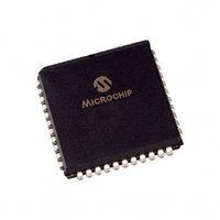
PIC16F871T-I/L Microchip Technology, PIC16F871T-I/L Datasheet - Page 477

PIC16F871T-I/L
Manufacturer Part Number
PIC16F871T-I/L
Description
IC MCU FLASH 2KX14 EE 44PLCC
Manufacturer
Microchip Technology
Series
PIC® 16Fr
Datasheets
1.PIC16F616T-ISL.pdf
(8 pages)
2.PIC16F688T-ISL.pdf
(688 pages)
3.PIC16F870-ISO.pdf
(172 pages)
4.PIC16F870-ISO.pdf
(6 pages)
Specifications of PIC16F871T-I/L
Core Processor
PIC
Core Size
8-Bit
Speed
20MHz
Connectivity
UART/USART
Peripherals
Brown-out Detect/Reset, POR, PWM, WDT
Number Of I /o
33
Program Memory Size
3.5KB (2K x 14)
Program Memory Type
FLASH
Eeprom Size
64 x 8
Ram Size
128 x 8
Voltage - Supply (vcc/vdd)
4 V ~ 5.5 V
Data Converters
A/D 8x10b
Oscillator Type
External
Operating Temperature
-40°C ~ 85°C
Package / Case
44-PLCC
Processor Series
PIC16F
Core
PIC
Data Bus Width
8 bit
Data Ram Size
128 B
Interface Type
PSP, USART
Maximum Clock Frequency
20 MHz
Number Of Programmable I/os
33
Number Of Timers
8
Operating Supply Voltage
2 V to 5.5 V
Maximum Operating Temperature
+ 85 C
Mounting Style
SMD/SMT
3rd Party Development Tools
52715-96, 52716-328, 52717-734
Development Tools By Supplier
PG164130, DV164035, DV244005, DV164005, PG164120, ICE2000, DM163022
Minimum Operating Temperature
- 40 C
On-chip Adc
28 bit
For Use With
I3-DB16F871 - BOARD DAUGHTER ICEPIC3
Lead Free Status / RoHS Status
Lead free / RoHS Compliant
Available stocks
Company
Part Number
Manufacturer
Quantity
Price
Company:
Part Number:
PIC16F871T-I/L
Manufacturer:
Microchip Technology
Quantity:
10 000
- PIC16F616T-ISL PDF datasheet
- PIC16F688T-ISL PDF datasheet #2
- PIC16F870-ISO PDF datasheet #3
- PIC16F870-ISO PDF datasheet #4
- Current page: 477 of 688
- Download datasheet (3Mb)
1997 Microchip Technology Inc.
Note:
COM0 - SEGx [ON] =
COM0 - SEGx [OFF] =
V
V
D = V
Refer to Figure 25-6
RMS
RMS
V
[ON] =
[OFF] =
RMS
RMS
[ON]
[OFF]
The next example is for Figure 25-6 which is a 1/4 MUX, 1/3 BIAS waveform. For this example,
the values 3, 2, 1 and 0 will be assigned to V
DC voltage, RMS voltage and discrimination ratio calculations are shown in
Example 25-4:
As shown in these examples, static displays have excellent contrast. The higher the multiplex
ratio of the LCD, the lower the discrimination ratio, and therefore, the lower the contrast of the
display.
Table 25-5
and BIAS.
As the multiplex of the LCD panel increases, the discrimination ratio decreases. The contrast of
the panel will also decrease, so to provide better contrast the LCD voltages must be increased
to provide greater separation between each level.
Table 25-5: Discrimination Ratio vs. MUX and Bias
1/2 MUX
1/3 MUX
1/4 MUX
STATIC
V
V
= 3
shows the V
1
3 - 3 + 1 - 1 + 1 - 1 + 1 - 1
1 - 1 - 1 + 1 - 1 + 1 - 1 + 1
(1)
(3)
2
2
V
V
Discrimination Ratio Calculation 1/4 MUX
+ (-1)
+ (-3)
0.333
0.333
0.333
V
= 1.732
OFF
0
OFF
2
2
+ (-1)
+ (1)
, V
ON
2
1/3 BIAS
2
+ (-1)
and discrimination ratios of the various combinations of MUX
0.745
0.638
0.577
+ (1)
V
1
ON
2
2
8
8
+ (-1)
+ (1)
3
2
2.236
1.915
1.732
, V
2
+ (-1)
D
+ (1)
2
, V
V
V
DC
DC
1
Section 25. LCD
2
2
, and V
+ (-1)
= 0
= 0
+ (1)
2
2
0
+ (-1)
+ (1)
respectively. The frame equation,
2
2
=
DS31025A-page 25-19
=
Example
3
V
V
25-4.
25
Related parts for PIC16F871T-I/L
Image
Part Number
Description
Manufacturer
Datasheet
Request
R

Part Number:
Description:
IC MCU FLASH 2KX14 EE 40DIP
Manufacturer:
Microchip Technology
Datasheet:

Part Number:
Description:
IC MCU FLASH 2KX14 EE 44PLCC
Manufacturer:
Microchip Technology
Datasheet:

Part Number:
Description:
IC MCU FLASH 2KX14 EE 44TQFP
Manufacturer:
Microchip Technology
Datasheet:

Part Number:
Description:
IC MCU CMOS 20MHZ 2K FLASH 40DIP
Manufacturer:
Microchip Technology
Datasheet:

Part Number:
Description:
IC MCU CMOS 20MHZ 2K FLSH 44PLCC
Manufacturer:
Microchip Technology
Datasheet:

Part Number:
Description:
IC MCU CMOS 20MHZ 2K FLSH 44TQFP
Manufacturer:
Microchip Technology
Datasheet:

Part Number:
Description:
28/40-pin, 8-bit Cmos Flash Microcontrollers
Manufacturer:
Microchip Technology Inc.
Datasheet:

Part Number:
Description:
IC MCU FLASH 4KX14 EEPROM 18DIP
Manufacturer:
Microchip Technology
Datasheet:

Part Number:
Description:
IC MCU FLASH 4KX14 EEPROM 18SOIC
Manufacturer:
Microchip Technology
Datasheet:

Part Number:
Description:
IC MCU FLASH 4KX14 EEPROM 20SSOP
Manufacturer:
Microchip Technology
Datasheet:

Part Number:
Description:
IC MCU FLASH 4KX14 EEPROM 28QFN
Manufacturer:
Microchip Technology
Datasheet:

Part Number:
Description:
IC MCU FLASH 4KX14 EEPROM 18SOIC
Manufacturer:
Microchip Technology
Datasheet:

Part Number:
Description:
IC MCU FLASH 4KX14 EEPROM 20SSOP
Manufacturer:
Microchip Technology
Datasheet:

Part Number:
Description:
IC MCU FLASH 4KX14 EEPROM 28QFN
Manufacturer:
Microchip Technology
Datasheet:

Part Number:
Description:
IC,MICROCONTROLLER,8-BIT,PIC CPU,CMOS,DIP,18PIN,PLASTIC
Manufacturer:
Microchip Technology
Datasheet:


