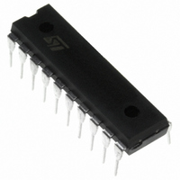
ST7FLITE25F1B6 STMicroelectronics, ST7FLITE25F1B6 Datasheet - Page 47

ST7FLITE25F1B6
Manufacturer Part Number
ST7FLITE25F1B6
Description
IC MCU 8BIT 8K FLASH 20-DIP
Manufacturer
STMicroelectronics
Series
ST7r
Specifications of ST7FLITE25F1B6
Core Processor
ST7
Core Size
8-Bit
Speed
8MHz
Connectivity
SPI
Peripherals
LVD, POR, PWM, WDT
Number Of I /o
15
Program Memory Size
8KB (8K x 8)
Program Memory Type
FLASH
Ram Size
384 x 8
Voltage - Supply (vcc/vdd)
2.4 V ~ 5.5 V
Data Converters
A/D 7x10b
Oscillator Type
Internal
Operating Temperature
-40°C ~ 85°C
Package / Case
20-DIP (0.300", 7.62mm)
Processor Series
ST7FLITE2x
Core
ST7
Data Bus Width
8 bit
Development Tools By Supplier
ST7FLITE-SK/RAIS, ST7MDT10-DVP3, ST7MDT10-EMU3, STX-RLINK
For Use With
497-5858 - EVAL BOARD PLAYBACK ST7FLITE
Lead Free Status / RoHS Status
Lead free / RoHS Compliant
Eeprom Size
-
Lead Free Status / Rohs Status
Details
Available stocks
Company
Part Number
Manufacturer
Quantity
Price
10.2.2 Output Modes
Setting the DDRx bit selects output mode. Writing
to the DR bits applies a digital value to the I/O
through the latch. Reading the DR bits returns the
previously stored value.
If an OR bit is available, different output modes
can be selected by software: push-pull or open-
drain. Refer to I/O Port Implementation section for
configuration.
DR Value and Output Pin Status
10.2.3 Alternate Functions
Many ST7s I/Os have one or more alternate func-
tions. These may include output signals from, or
– disable the external interrupt through the OR
– select rising edge
– reset the interrupt mask with the RIM instruc-
register
tion (in cases where a pin level change could
occur)
DR
0
1
Push-Pull
V
V
OH
OL
Open-Drain
Floating
V
OL
input signals to, on-chip peripherals. The Device
Pin Description table describes which peripheral
signals can be input/output to which ports.
A signal coming from an on-chip peripheral can be
output on an I/O. To do this, enable the on-chip
peripheral as an output (enable bit in the peripher-
al’s control register). The peripheral configures the
I/O as an output and takes priority over standard I/
O programming. The I/O’s state is readable by ad-
dressing the corresponding I/O data register.
Configuring an I/O as floating enables alternate
function input. It is not recommended to configure
an I/O as pull-up as this will increase current con-
sumption. Before using an I/O as an alternate in-
put, configure it without interrupt. Otherwise spuri-
ous interrupts can occur.
Configure an I/O as input floating for an on-chip
peripheral signal which can be input and output.
Caution:
I/Os which can be configured as both an analog
and digital alternate function need special atten-
tion. The user must control the peripherals so that
the signals do not arrive at the same time on the
same pin. If an external clock is used, only the
clock alternate function should be employed on
that I/O pin and not the other alternate function.
ST7LITE2
47/133
1


