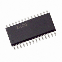
Z86E3116SSG Zilog, Z86E3116SSG Datasheet - Page 48

Z86E3116SSG
Manufacturer Part Number
Z86E3116SSG
Description
IC MICROCONTROLLER 2K 28-SOIC
Manufacturer
Zilog
Series
Z8®r
Datasheet
1.Z86E4001ZDV.pdf
(64 pages)
Specifications of Z86E3116SSG
Core Processor
Z8
Core Size
8-Bit
Speed
16MHz
Peripherals
POR, WDT
Number Of I /o
24
Program Memory Size
2KB (2K x 8)
Program Memory Type
OTP
Ram Size
125 x 8
Voltage - Supply (vcc/vdd)
3.5 V ~ 5.5 V
Oscillator Type
Internal
Operating Temperature
0°C ~ 70°C
Package / Case
28-SOIC (7.5mm Width)
Processor Series
Z86E3xx
Core
Z8
Data Bus Width
8 bit
Data Ram Size
125 B
Maximum Clock Frequency
8 MHz
Number Of Programmable I/os
24
Number Of Timers
2
Operating Supply Voltage
3.5 V to 5.5 V
Maximum Operating Temperature
+ 70 C
Mounting Style
SMD/SMT
Minimum Operating Temperature
0 C
Lead Free Status / RoHS Status
Lead free / RoHS Compliant
Eeprom Size
-
Data Converters
-
Connectivity
-
Lead Free Status / Rohs Status
Details
Other names
269-3968
Z86E3116SSG
Z86E3116SSG
FUNCTIONAL DESCRIPTION (Continued)
Z86E30/E31/E40
Z8 4K OTP Microcontroller
EPROM MODE
Table 14 shows the programming voltages of each pro-
gramming mode. Table 15, and figures that follow show
the programming timing of each programming mode. Fig-
ure 38 shows the circuit diagram of a Z86E40 program-
ming adapter, which adapts from 2764A to Z86E40 and
Figure 39 shows the Z86E30/E31 Programming Adapter
Circuitry. Figure 40 shows the flowchart of an Intelligent
Programming Algorithm, which is compatible with 2764A
EPROM (Z86E40 is 4K EPROM, 2764A is 8K EPROM).
Since the EPROM size of Z86E30/E31/E40 differs from
2764A, the programming address range has to be set from
0000H to 0FFFH for the Z86E30/E40 and 0000H to 07FFH
for Z86E31. Otherwise, the upper portion of EPROM data
will overwrite the lower portion of EPROM data. Figure 39
shows the adaptation from the 2764A to Z86E30/E31.
Note: EPROM Protect feature allows the LDC, LDCI, LDE,
and LDEI instructions from internal program memory. A
ROM lookup table can be used with this feature.
During programming, the V
gramming voltage and current to the EPROM. This pin is
also used to latch which EPROM mode is to be used (R/W
EPROM or R/W Option bits). The mode is set by placing
the correct mode number on the least significant bits of the
address and raising the EPM pin above V. After a setup
time, the V
latched EPROM mode will remain until the EPM pin is re-
duced below V
EPROM R/W
Option Bit R/W
48
Mode Name
PP
H
pin can then be raised or lowered. The
.
Mode #
PP
0
3
input pin supplies the pro-
LSB Addr
0000
0011
P R E L I M I N A R Y
EPROM R/W mode allows the programming of the user
mode program ROM.
Option Bit R/W allows the programming of the Z8 option
bits. When the device is latched into Option Bit R/W mode,
the address must then be changed to 63 decimals
(000000111111 Binary). The Options are mapped into this
address as follows:
Table 14 gives the proper conditions for EPROM R/W op-
erations, once the mode is latched.
Bit
7
6
5
4
3
2
1
0
Option
Unused
Unused
32 KHz XTAL Option
Permanent WDT
Auto Latch Disable
RC Oscillator Option
RAM Protect
ROM Protect
DS97Z8X0502
Zilog


