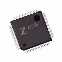
Z8F4822AR020EC Zilog, Z8F4822AR020EC Datasheet - Page 60

Z8F4822AR020EC
Manufacturer Part Number
Z8F4822AR020EC
Description
IC ENCORE MCU FLASH 48K 64LQFP
Manufacturer
Zilog
Series
Encore!® XP®r
Specifications of Z8F4822AR020EC
Core Processor
Z8
Core Size
8-Bit
Speed
20MHz
Connectivity
I²C, IrDA, SPI, UART/USART
Peripherals
Brown-out Detect/Reset, DMA, POR, PWM, WDT
Number Of I /o
46
Program Memory Size
48KB (48K x 8)
Program Memory Type
FLASH
Ram Size
4K x 8
Voltage - Supply (vcc/vdd)
3 V ~ 3.6 V
Data Converters
A/D 12x10b
Oscillator Type
Internal
Operating Temperature
-40°C ~ 105°C
Package / Case
64-LQFP
Lead Free Status / RoHS Status
Contains lead / RoHS non-compliant
Eeprom Size
-
Other names
269-3289
Available stocks
Company
Part Number
Manufacturer
Quantity
Price
- Current page: 60 of 297
- Download datasheet (9Mb)
Reset Sources
Table 9. Reset Sources and Resulting Reset Type
PS019921-0308
Operating Mode
NORMAL or HALT
modes
STOP mode
System Reset
During a system reset, the Z8 Encore! XP F64XX Series devices are held in Reset for 66
cycles of the Watchdog Timer oscillator followed by 16 cycles of the system clock. At the
beginning of Reset, all GPIO pins are configured as inputs.
During Reset, the eZ8 CPU and on-chip peripherals are idle; however, the on-chip crystal
oscillator and Watchdog Timer oscillator continue to run. The system clock begins
operating following the Watchdog Timer oscillator cycle count. The eZ8 CPU and on-chip
peripherals remain idle through the 16 cycles of the system clock.
Upon Reset, control registers within the Register File that have a defined Reset value are
loaded with their reset values. Other control registers (including the Stack Pointer,
Register Pointer, and Flags) and general-purpose RAM are undefined following Reset.
The eZ8 CPU fetches the Reset vector at Program Memory addresses
and loads that value into the Program Counter. Program execution begins at the Reset
vector address.
Table 9
vides more detailed information on the individual Reset sources. A Power-On Reset/Volt-
age Brownout event always takes priority over all other possible reset sources to ensure a
full system reset occurs.
Reset Source
Power-On Reset/Voltage
Brownout
Watchdog Timer time-out
when configured for Reset
RESET pin assertion
On-Chip Debugger initiated Reset
(OCDCTL[0] set to 1)
Power-On Reset/Voltage
Brownout
RESET pin assertion
DBG pin driven Low
lists the reset sources as a function of the operating mode. The text following pro-
system reset
system reset
system reset
Reset Type
system reset
system reset
system reset except the On-Chip Debugger is
unaffected by the reset
system reset
Z8 Encore! XP
Reset and Stop Mode Recovery
Product Specification
0002H
®
F64XX Series
and
0003H
46
Related parts for Z8F4822AR020EC
Image
Part Number
Description
Manufacturer
Datasheet
Request
R

Part Number:
Description:
Communication Controllers, ZILOG INTELLIGENT PERIPHERAL CONTROLLER (ZIP)
Manufacturer:
Zilog, Inc.
Datasheet:

Part Number:
Description:
KIT DEV FOR Z8 ENCORE 16K TO 64K
Manufacturer:
Zilog
Datasheet:

Part Number:
Description:
KIT DEV Z8 ENCORE XP 28-PIN
Manufacturer:
Zilog
Datasheet:

Part Number:
Description:
DEV KIT FOR Z8 ENCORE 8K/4K
Manufacturer:
Zilog
Datasheet:

Part Number:
Description:
KIT DEV Z8 ENCORE XP 28-PIN
Manufacturer:
Zilog
Datasheet:

Part Number:
Description:
DEV KIT FOR Z8 ENCORE 4K TO 8K
Manufacturer:
Zilog
Datasheet:

Part Number:
Description:
CMOS Z8 microcontroller. ROM 16 Kbytes, RAM 256 bytes, speed 16 MHz, 32 lines I/O, 3.0V to 5.5V
Manufacturer:
Zilog, Inc.
Datasheet:

Part Number:
Description:
Low-cost microcontroller. 512 bytes ROM, 61 bytes RAM, 8 MHz
Manufacturer:
Zilog, Inc.
Datasheet:

Part Number:
Description:
Z8 4K OTP Microcontroller
Manufacturer:
Zilog, Inc.
Datasheet:

Part Number:
Description:
CMOS SUPER8 ROMLESS MCU
Manufacturer:
Zilog, Inc.
Datasheet:

Part Number:
Description:
SL1866 CMOSZ8 OTP Microcontroller
Manufacturer:
Zilog, Inc.
Datasheet:

Part Number:
Description:
SL1866 CMOSZ8 OTP Microcontroller
Manufacturer:
Zilog, Inc.
Datasheet:

Part Number:
Description:
OTP (KB) = 1, RAM = 125, Speed = 12, I/O = 14, 8-bit Timers = 2, Comm Interfaces Other Features = Por, LV Protect, Voltage = 4.5-5.5V
Manufacturer:
Zilog, Inc.
Datasheet:

Part Number:
Description:
Manufacturer:
Zilog, Inc.
Datasheet:


