STM32F103CBT7 STMicroelectronics, STM32F103CBT7 Datasheet - Page 52
STM32F103CBT7
Manufacturer Part Number
STM32F103CBT7
Description
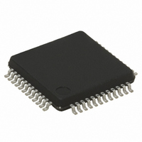
MCU ARM 32BIT 64KB FLASH 48LQFP
Manufacturer
STMicroelectronics
Series
STM32r
Datasheet
1.STM32F103R8H6.pdf
(99 pages)
Specifications of STM32F103CBT7
Core Processor
ARM® Cortex-M3™
Core Size
32-Bit
Speed
72MHz
Connectivity
CAN, I²C, IrDA, LIN, SPI, UART/USART, USB
Peripherals
DMA, Motor Control PWM, PDR, POR, PVD, PWM, Temp Sensor, WDT
Number Of I /o
37
Program Memory Size
128KB (128K x 8)
Program Memory Type
FLASH
Ram Size
20K x 8
Voltage - Supply (vcc/vdd)
2 V ~ 3.6 V
Data Converters
A/D 10x12b
Oscillator Type
Internal
Operating Temperature
-40°C ~ 105°C
Package / Case
48-LQFP
Processor Series
STM32F103x
Core
ARM Cortex M3
Data Bus Width
32 bit
Data Ram Size
20 KB
Interface Type
CAN, I2C, SPI, USART, USB
Maximum Clock Frequency
72 MHz
Number Of Programmable I/os
37
Number Of Timers
4
Maximum Operating Temperature
+ 105 C
Mounting Style
SMD/SMT
3rd Party Development Tools
EWARM, EWARM-BL, MDK-ARM, RL-ARM, ULINK2
Minimum Operating Temperature
- 40 C
On-chip Adc
2 (12 bit, 10 Channel)
Featured Product
STM32 Cortex-M3 Companion Products
Eeprom Size
-
For Use With
497-10048 - BOARD EVAL ACCELEROMETER497-10030 - STARTER KIT FOR STM32KSDKSTM32-PL - KIT IAR KICKSTART STM32 CORTEXM3497-8512 - KIT STARTER FOR STM32F10XE MCU497-8511 - KIT STARTER FOR STM32 512K FLASH497-8505 - KIT STARTER FOR STM32F10XE MCU497-6438 - BOARD EVALUTION FOR STM32 512K497-6289 - KIT PERFORMANCE STICK FOR STM32MCBSTM32UME - BOARD EVAL MCBSTM32 + ULINK-MEMCBSTM32U - BOARD EVAL MCBSTM32 + ULINK2MCBSTM32 - BOARD EVAL FOR STM STM32X SER497-6053 - KIT STARTER FOR STM32497-6052 - KIT STARTER FOR STM32497-6050 - KIT STARTER FOR STM32497-6049 - KIT EVALUATION LOW COST STM32497-6048 - BOARD EVALUATION FOR STM32497-6047 - KIT DEVELOPMENT FOR STM32
Lead Free Status / RoHS Status
Lead free / RoHS Compliant
Eeprom Size
-
Lead Free Status / Rohs Status
Details
Available stocks
Company
Part Number
Manufacturer
Quantity
Price

Company:
Part Number:
STM32F103CBT7
Manufacturer:
LT
Quantity:
10
Company:
Part Number:
STM32F103CBT7
Manufacturer:
STMicroelectronics
Quantity:
10 000
Company:
Part Number:
STM32F103CBT7TR
Manufacturer:
KELI
Quantity:
1 000
Company:
Part Number:
STM32F103CBT7TR
Manufacturer:
STMicroelectronics
Quantity:
10 000


Electrical characteristics
Table 23.
1. Based on characterization, not tested in production.
2. Refer to the note and caution paragraphs below the table, and to the application note AN2867 “Oscillator design guide for
3.
Note:
Caution:
52/99
t
SU(LSE)
Symbol
ST microcontrollers”.
reached. This value is measured for a standard crystal and it can vary significantly with the crystal manufacturer
t
SU(LSE)
R
g
C
I
2
m
F
(3)
is the startup time measured from the moment it is enabled (by software) to a stabilized 32.768 kHz oscillation is
LSE oscillator characteristics (f
For C
15 pF range selected to match the requirements of the crystal or resonator. C
usually the same size. The crystal manufacturer typically specifies a load capacitance which
is the series combination of C
Load capacitance C
C
between 2 pF and 7 pF.
To avoid exceeding the maximum value of C
to use a resonator with a load capacitance C
capacitance of 12.5 pF.
Example: if you choose a resonator with a load capacitance of C
then C
Feedback resistor
Recommended load capacitance
versus equivalent serial
resistance of the crystal (R
LSE driving current
Oscillator transconductance
Startup time
stray
L1
is the pin capacitance and board or trace PCB-related capacitance. Typically, it is
L1
and C
= C
Parameter
L2
L2
= 8 pF.
it is recommended to use high-quality ceramic capacitors in the 5 pF to
L
has the following formula: C
S
)
L1
Doc ID 13587 Rev 13
and C
V
Conditions
R
LSE
V
stabilized
DD
S
IN
V
= 30 KΩ
DD
= 3.3 V
= 32.768 kHz)
= V
L2
is
.
SS
L1
L
≤
and C
7 pF. Never use a resonator with a load
T
T
T
T
L
T
T
T
T
A
A
A
A
A
A
A
= C
A
(1) (2)
= -10 °C
= -20 °C
= -30 °C
= -40 °C
= 50 °C
= 25 °C
= 10 °C
L2
= 0 °C
L1
(15 pF) it is strongly recommended
x C
STM32F103x8, STM32F103xB
L2
/ (C
L
Min
= 6 pF, and C
5
L1
+ C
Typ
1.5
2.5
10
17
32
60
L2
5
4
6
) + C
L1
and C
Max
stray
1.4
15
stray
= 2 pF,
L2,
where
µA/V
Unit
MΩ
pF
µA
are
s
Related parts for STM32F103CBT7
Image
Part Number
Description
Manufacturer
Datasheet
Request
R

Part Number:
Description:
DEV KIT FOR STM32
Manufacturer:
STMicroelectronics
Datasheet:

Part Number:
Description:
MCU ARM 128KB FLASH MEM 64-LQFP
Manufacturer:
STMicroelectronics
Datasheet:

Part Number:
Description:
MCU ARM 32BIT 128KB FLASH 64BGA
Manufacturer:
STMicroelectronics
Datasheet:

Part Number:
Description:
MCU ARM 32BIT 256K FLASH 144LQFP
Manufacturer:
STMicroelectronics
Datasheet:

Part Number:
Description:
KIT STARTER FOR STM32F10X
Manufacturer:
STMicroelectronics
Datasheet:

Part Number:
Description:
MCU ARM 128K FLASH/TIMER
Manufacturer:
STMicroelectronics
Datasheet:

Part Number:
Description:
MCU ARM 128KB FLASH MEM 100-LQFP
Manufacturer:
STMicroelectronics
Datasheet:

Part Number:
Description:
MCU 32BIT ARM 64K FLASH 36VFQFPN
Manufacturer:
STMicroelectronics
Datasheet:
Part Number:
Description:
MCU ARM 32BIT 32KB FLASH 48LQFP
Manufacturer:
STMicroelectronics
Datasheet:
Part Number:
Description:
MCU ARM 32BIT 64KB FLASH 64LQFP
Manufacturer:
STMicroelectronics
Datasheet:
Part Number:
Description:
MCU ARM 32BIT 384KB FLASH 64LQFP
Manufacturer:
STMicroelectronics
Datasheet:

Part Number:
Description:
MCU 32BIT ARM 512K FLASH 100-LQF
Manufacturer:
STMicroelectronics
Datasheet:
Part Number:
Description:
MCU ARM 32BIT 512KB FLASH 144BGA
Manufacturer:
STMicroelectronics
Datasheet:
Part Number:
Description:
MCU ARM 32BIT 512K FLASH 144LQFP
Manufacturer:
STMicroelectronics
Datasheet:
Part Number:
Description:
MCU 32BIT ARM 16K FLASH 64LQFP
Manufacturer:
STMicroelectronics
Datasheet: