STM32F103RBT7TR STMicroelectronics, STM32F103RBT7TR Datasheet - Page 89
STM32F103RBT7TR
Manufacturer Part Number
STM32F103RBT7TR
Description
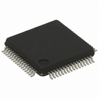
MCU ARM 32BIT 64KB FLASH 64LQFP
Manufacturer
STMicroelectronics
Series
STM32r
Datasheets
1.STM32F103RBT7TR.pdf
(92 pages)
2.STM32F103C8T6TR.pdf
(99 pages)
3.STM32F103C8T6TR.pdf
(67 pages)
Specifications of STM32F103RBT7TR
Core Processor
ARM® Cortex-M3™
Core Size
32-Bit
Speed
72MHz
Connectivity
CAN, I²C, IrDA, LIN, SPI, UART/USART, USB
Peripherals
DMA, Motor Control PWM, PDR, POR, PVD, PWM, Temp Sensor, WDT
Number Of I /o
51
Program Memory Size
128KB (128K x 8)
Program Memory Type
FLASH
Ram Size
20K x 8
Voltage - Supply (vcc/vdd)
2 V ~ 3.6 V
Data Converters
A/D 16x12b
Oscillator Type
Internal
Operating Temperature
-40°C ~ 105°C
Package / Case
64-LQFP
Processor Series
STM32F103x
Core
ARM Cortex M3
Data Bus Width
32 bit
Data Ram Size
20 KB
Interface Type
CAN, I2C, SPI, USART, USB
Maximum Clock Frequency
72 MHz
Number Of Programmable I/os
51
Number Of Timers
4
Maximum Operating Temperature
+ 105 C
Mounting Style
SMD/SMT
3rd Party Development Tools
EWARM, EWARM-BL, KSDK-STM32-PLUS, KSK-STM32-JL, MDK-ARM, RL-ARM, ULINK2
Development Tools By Supplier
ST-LINK
Minimum Operating Temperature
- 40 C
On-chip Adc
2 (12 bit, 16 Channel)
For Use With
497-10048 - BOARD EVAL ACCELEROMETER497-10030 - STARTER KIT FOR STM32KSDKSTM32-PL - KIT IAR KICKSTART STM32 CORTEXM3497-8512 - KIT STARTER FOR STM32F10XE MCU497-8511 - KIT STARTER FOR STM32 512K FLASH497-8505 - KIT STARTER FOR STM32F10XE MCU497-8418 - BOARD DEMO DGTL PHOTOFRAME STM32497-6438 - BOARD EVALUTION FOR STM32 512K497-6289 - KIT PERFORMANCE STICK FOR STM32MCBSTM32UME - BOARD EVAL MCBSTM32 + ULINK-MEMCBSTM32U - BOARD EVAL MCBSTM32 + ULINK2MCBSTM32 - BOARD EVAL FOR STM STM32X SER497-6053 - KIT STARTER FOR STM32497-6052 - KIT STARTER FOR STM32497-6050 - KIT STARTER FOR STM32497-6049 - KIT EVALUATION LOW COST STM32497-6048 - BOARD EVALUATION FOR STM32497-6047 - KIT DEVELOPMENT FOR STM32
Lead Free Status / RoHS Status
Lead free / RoHS Compliant
Eeprom Size
-
Lead Free Status / Rohs Status
Details
Available stocks
Company
Part Number
Manufacturer
Quantity
Price
Company:

Part Number:
STM32F103RBT7TR
Manufacturer:
STMicroelectronics
Quantity:
10 000


STM32F103x8, STM32F103xB
Table 58.
22-May-2008
14-Mar-2008
21-Mar-2008
Date
Document revision history (continued)
Revision
5
6
7
Figure 2: Clock tree on page 20
Maximum T
page
CRC feature added (see
unit on page 9
I
Stop and Standby
ACC
note 2 removed.
P
in
t
V
page
Table 41: SPI characteristics on page 64
I
Table 47: ADC accuracy - limited test conditions
accuracy
LQFP100 package specifications updated (see
characteristics on page
Recommended LQFP100, LQFP 64, LQFP48 and VFQFPN36
footprints added (see
Section 6.2: Thermal characteristics on page 82
Section 6.2.1
Appendix A: Important notes on page 81
Small text changes.
In
– N
– cycling conditions specified for t
– t
V
CRC feature removed.
CRC feature added back. Small text changes.
modified.
I
current consumptions in Stop and Standby modes on page
I
Standby mode on page
Values added to
3.3 V) on page
Figure 27: SPI timing diagram - slave mode and CPHA = 0 on page 65
modified.
t
data retention on page
V
Figure 47: LQFP100 PD max vs. TA on page 84
Axx option added to
page
DD
RET
VREF
DD
DD_VBAT
RET
D
NF(NRST)
25
USB
Table 28: Flash memory characteristics on page
Table 29: Flash memory endurance and data
, T
RET
Doc ID 13587 Rev 11
, Avg_Slope and T
modified in
END
at T
HSI
modified in
at T
A
35.
60.
85.
added to
added to
and T
min modified at T
A
modified in
tested over the whole temperature range
A
removed from
max = 105 °C added to
modified.
Section 2.2: Full compatibility throughout the family
Equation 1
= 105 °C modified in
unit corrected in
J
J
value given in
added, t
and
and
Table 16: Typical and maximum current consumptions in
Table 43: USB DC electrical characteristics on page
63.
Table 45: ADC characteristics on page
Table 29: Flash memory endurance and data
Table 40: SCL frequency (fPCLK1= 36 MHz.,VDD =
Section 6.2.2
modes.
Figure 9: Memory map on page 31
Table 24: HSI oscillator characteristics on page
Figure 9: Memory map
Table 57: Ordering information scheme on
corrected.
Figure
prog
L
54.
modified in
Table 21: Typical current consumption in
73).
A
47.
CRC (cyclic redundancy check) calculation
= 55 °C
values modified and t
Table 37: NRST pin characteristics on
Table 8: Thermal characteristics on
40,
Changes
Table 29: Flash memory endurance and
added.
added.
Figure
Table 16: Typical and maximum
RET
Table 49: TS
42,
modified.
removed.
Figure 46
clarified.
Section 1: Introduction
prog
Section 6: Package
retention:
added.
characteristics.
modified.
modified,
53.
description clarified
Revision history
and
68.
for address).
Table 48: ADC
Figure
42.
added.
retention.
36).
89/92
52,
67.
Related parts for STM32F103RBT7TR
Image
Part Number
Description
Manufacturer
Datasheet
Request
R

Part Number:
Description:
STMicroelectronics [RIPPLE-CARRY BINARY COUNTER/DIVIDERS]
Manufacturer:
STMicroelectronics
Datasheet:
Part Number:
Description:
STMicroelectronics [LIQUID-CRYSTAL DISPLAY DRIVERS]
Manufacturer:
STMicroelectronics
Datasheet:

Part Number:
Description:
BOARD EVAL FOR MEMS SENSORS
Manufacturer:
STMicroelectronics
Datasheet:
Part Number:
Description:
NPN TRANSISTOR POWER MODULE
Manufacturer:
STMicroelectronics
Datasheet:
Part Number:
Description:
TURBOSWITCH ULTRA-FAST HIGH VOLTAGE DIODE
Manufacturer:
STMicroelectronics
Datasheet:
Part Number:
Description:
Manufacturer:
STMicroelectronics
Datasheet:
Part Number:
Description:
DIODE / SCR MODULE
Manufacturer:
STMicroelectronics
Datasheet:
Part Number:
Description:
DIODE / SCR MODULE
Manufacturer:
STMicroelectronics
Datasheet:
Part Number:
Description:
Search -----> STE16N100
Manufacturer:
STMicroelectronics
Datasheet:
Part Number:
Description:
Search ---> STE53NA50
Manufacturer:
STMicroelectronics
Datasheet:
Part Number:
Description:
NPN Transistor Power Module
Manufacturer:
STMicroelectronics
Datasheet:
Part Number:
Description:
DIODE / SCR MODULE
Manufacturer:
STMicroelectronics
Datasheet: