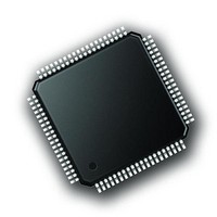
STR911FAM47X6T STMicroelectronics, STR911FAM47X6T Datasheet - Page 36

STR911FAM47X6T
Manufacturer Part Number
STR911FAM47X6T
Description
MCU ARM9 2048KB FLASH 80LQFP
Manufacturer
STMicroelectronics
Series
STR9r
Datasheet
1.STEVAL-IFW001V1.pdf
(102 pages)
Specifications of STR911FAM47X6T
Core Processor
ARM9
Core Size
32-Bit
Speed
96MHz
Connectivity
CAN, I²C, IrDA, Microwire, SPI, SSP, UART/USART, USB
Peripherals
Brown-out Detect/Reset, DMA, POR, PWM, WDT
Number Of I /o
40
Program Memory Size
2MB (2M x 8)
Program Memory Type
FLASH
Ram Size
96K x 8
Voltage - Supply (vcc/vdd)
1.65 V ~ 2 V
Data Converters
A/D 8x10b
Oscillator Type
Internal
Operating Temperature
-40°C ~ 85°C
Package / Case
80-LQFP
Processor Series
STR911x
Core
ARM966E-S
Data Bus Width
16 bit, 32 bit
Data Ram Size
96 KB
Interface Type
CAN, SPI, UART
Maximum Clock Frequency
96 MHz
Number Of Programmable I/os
40
Number Of Timers
4
Maximum Operating Temperature
+ 85 C
Mounting Style
SMD/SMT
3rd Party Development Tools
EWARM, EWARM-BL, MCBSTR9, MCBSTR9U, MCBSTR9UME, MDK-ARM, RL-ARM, ULINK2
Minimum Operating Temperature
- 40 C
On-chip Adc
10 bit, 8 Channel
For Use With
MCBSTR9UME - BOARD EVAL MCBSTR9 + ULINK-MEMCBSTR9U - BOARD EVAL MCBSTR9 + ULINK2MCBSTR9 - BOARD EVAL STM STR9 SERIES
Lead Free Status / RoHS Status
Lead free / RoHS Compliant
Eeprom Size
-
Lead Free Status / Rohs Status
Details
Available stocks
Company
Part Number
Manufacturer
Quantity
Price
Company:
Part Number:
STR911FAM47X6T
Manufacturer:
STMicroelectronics
Quantity:
10 000
Functional overview
3.24.1
3.25
3.25.1
36/102
DMA
A programmable DMA channel may be assigned by CPU firmware to service each ADC
conversion result for fast DMA single-transfer.
Standard timers (TIM) with DMA
The STR91xFA has four independent, free-running 16-bit timer/counter modules designated
TIM0, TIM1, TIM2, and TIM3. Each general purpose timer/counter can be configured by
firmware for a variety of tasks including; pulse width and frequency measurement (input
capture), generation of waveforms (output compare and PWM), event counting, delay
timing, and up/down counting.
Each of the four timer units have the following features:
●
●
●
●
●
●
●
●
●
DMA
A programmable DMA channel may be assigned by CPU firmware to service each
timer/counter module TIM0 and TIM1 for fast and direct single transfers.
16-bit free running timer/counter
Internal timer/counter clock source from a programmable 8-bit prescale of the CCU
PCLK clock output
Optional external timer/counter clock source from pin P2.4 shared by TIM0/TIM1, and
pin P2.5 shared by TIM2/TIM3. Frequency of these external clocks must be at least 4
times less the frequency of the internal CCU PCLK clock output.
Two dedicated 16-bit Input Capture registers for measuring up to two input signals.
Input Capture has programmable selection of input signal edge detection
Two dedicated 16-bit Output Compare registers for generation up to two output signals
PWM output generation with 16-bit resolution of both pulse width and frequency
One pulse generation in response to an external event
A dedicated interrupt to the CPU with five interrupt flags
The OCF1 flag (Output Compare 1) from the timer can be configured to trigger an ADC
conversion
Doc ID 13495 Rev 6
STR91xFAxxx


