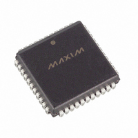
DS80C323-QCD Maxim Integrated Products, DS80C323-QCD Datasheet - Page 14

DS80C323-QCD
Manufacturer Part Number
DS80C323-QCD
Description
IC MCU HI SPEED 18MHZ 44-PLCC
Manufacturer
Maxim Integrated Products
Series
80Cr
Datasheet
1.DS80C323-QND.pdf
(38 pages)
Specifications of DS80C323-QCD
Core Processor
8051
Core Size
8-Bit
Speed
18MHz
Connectivity
EBI/EMI, SIO, UART/USART
Peripherals
Power-Fail Reset, WDT
Number Of I /o
32
Program Memory Type
ROMless
Ram Size
256 x 8
Voltage - Supply (vcc/vdd)
4.5 V ~ 5.5 V
Oscillator Type
External
Operating Temperature
0°C ~ 70°C
Package / Case
44-LCC, 44-PLCC
Processor Series
DS80C323
Core
8051
Data Bus Width
8 bit
Program Memory Size
64 KB
Data Ram Size
64 KB
Interface Type
UART
Maximum Clock Frequency
18 MHz
Number Of Programmable I/os
32
Number Of Timers
3
Operating Supply Voltage
2.7 V to 5.5 V
Maximum Operating Temperature
+ 70 C
Mounting Style
SMD/SMT
3rd Party Development Tools
PK51, CA51, A51, ULINK2
Minimum Operating Temperature
0 C
Lead Free Status / RoHS Status
Contains lead / RoHS non-compliant
Eeprom Size
-
Program Memory Size
-
Data Converters
-
Available stocks
Company
Part Number
Manufacturer
Quantity
Price
Company:
Part Number:
DS80C323-QCD
Manufacturer:
DALLAS
Quantity:
318
Company:
Part Number:
DS80C323-QCD
Manufacturer:
Maxim Integrated
Quantity:
10 000
Company:
Part Number:
DS80C323-QCD+
Manufacturer:
MAXIM
Quantity:
379
Company:
Part Number:
DS80C323-QCD+
Manufacturer:
Maxim Integrated
Quantity:
10 000
Company:
Part Number:
DS80C323-QCD+T&R
Manufacturer:
Maxim Integrated
Quantity:
10 000
Company:
Part Number:
DS80C323-QCD/T&R
Manufacturer:
Maxim Integrated
Quantity:
10 000
64-Byte Block Move with Dual Data Pointer
; SH and SL are high and low byte source address.
; DH and DL are high and low byte of destination address.
; DPS is the data pointer select. Reset condition is DPS=0, DPTR0 is selected.
EQU
MOV
MOV
INC
MOV
MOVE:
; THIS LOOP IS PERFORMED THE NUMBER OF TIMES LOADED INTO R5, IN THIS EXAMPLE 64
MOVX
INC
MOVX
INC
INC
INC
DJNZ
PERIPHERAL OVERVIEW
Peripherals in the DS80C320/DS80C323 are accessed using the SFRs. The devices provide several of the
most commonly needed peripheral functions in microcomputer-based systems. These functions are new
to the 80C32 family and include a second serial port, power-fail reset, power-fail interrupt, and a
programmable watchdog timer. These are briefly described in the following paragraphs. More details are
available in the High-Speed Microcontroller User’s Guide.
SERIAL PORTS
The DS80C320/DS80C323 provide a serial port (UART) that is identical to the 80C32. Many
applications require serial communication with multiple devices. Therefore, a second hardware serial port
is provided that is a full duplicate of the standard one. It optionally uses pins P1.2 (RXD1) and P1.3
(TXD1). This port has duplicate control functions included in new SFR locations. The second serial port
operates in a comparable manner with the first. Both can operate simultaneously but can be at different
baud rates.
The second serial port has similar control registers (SCON1 at C0h, SBUF1 at C1h) to the original. One
difference is that for timer-based baud rates, the original serial port can use Timer 1 or Timer 2 to
generate baud rates. This is selected via SFR bits. The new serial port can only use Timer 1.
TIMER-RATE CONTROL
One important difference exists between the DS80C320/DS80C323 and 80C32 regarding timers. The
original 80C32 used a 12 clock-per-cycle scheme for timers and consequently for some serial baud rates
(depending on the mode). The DS80C320/DS80C323 architecture normally runs using 4 clocks per cycle.
However, in the area of timers, it will default to a 12 clock-per-cycle scheme on a reset. This allows
existing code with real-time dependencies such as baud rates to operate properly. If an application needs
higher speed timers or serial baud rates, the timers can be set to run at the 4-clock rate.
The Clock Control register (CKCON - 8Eh) determines these timer speeds. When the relevant CKCON
bit is a logic 1, the device uses 4 clocks per cycle to generate timer speeds. When the control bit is set to a
0, the device uses 12 clocks for timer speeds. The reset condition is a 0. CKCON.5 selects the speed of
Timer 2. CKCON.4 selects Timer 1 and CKCON.3 selects Timer 0. Note that unless a user desires very
fast timing, it is unnecessary to alter these bits. Note that the timer controls are independent.
DPS, #86h
R5, #64
DPTR, #DHDL
DPS
DPTR, #SHSL
A, @DPTR
DPS
@DPTR, A
DPTR
DPS
DPTR
R5, MOVE
; TELL ASSEMBLER ABOUT DPS
; NUMBER OF BYTES TO MOVE
; LOAD DESTINATION ADDRESS
; CHANGE ACTIVE DPTR
; LOAD SOURCE ADDRESS
; READ SOURCE DATA BYTE
; CHANGE DPTR TO DESTINATION
; WRITE DATA TO DESTINATION
; NEXT DESTINATION ADDRESS
; CHANGE DATA POINTER TO SOURCE
; NEXT SOURCE ADDRESS
; FINISHED WITH TABLE?
DS80C320/DS80C323 High-Speed/Low-Power Microcontrollers
14 of 38
# CYCLES
2
3
2
2
2
2
2
3
2
3
3


