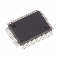
DS5000FP-16+ Maxim Integrated Products, DS5000FP-16+ Datasheet - Page 7

DS5000FP-16+
Manufacturer Part Number
DS5000FP-16+
Description
IC MODULE MICRO 16MHZ 80-QFP
Manufacturer
Maxim Integrated Products
Series
DS500xr
Datasheet
1.DS5000FP-16.pdf
(22 pages)
Specifications of DS5000FP-16+
Core Processor
8051
Core Size
8-Bit
Speed
16MHz
Connectivity
EBI/EMI, SIO, UART/USART
Peripherals
Power-Fail Reset, WDT
Number Of I /o
32
Program Memory Type
SRAM
Ram Size
128 x 8
Voltage - Supply (vcc/vdd)
4.75 V ~ 5.25 V
Oscillator Type
External
Operating Temperature
0°C ~ 70°C
Package / Case
80-MQFP, 80-PQFP
Processor Series
DS5000
Core
8051
Data Bus Width
8 bit
Program Memory Size
8 KB to 64 KB
Data Ram Size
8 KB to 64 KB
Interface Type
3-Wire, RS-232, UART
Maximum Clock Frequency
16 MHz
Number Of Programmable I/os
32
Number Of Timers
2
Operating Supply Voltage
4.75 V to 5.25 V
Maximum Operating Temperature
+ 70 C
Mounting Style
SMD/SMT
Development Tools By Supplier
DS5000TK
Minimum Operating Temperature
0 C
Lead Free Status / RoHS Status
Lead free / RoHS Compliant
Eeprom Size
-
Program Memory Size
-
Data Converters
-
Lead Free Status / Rohs Status
Details
POWER MANAGEMENT
The DS5000FP monitors power to provide Power-Fail Reset, early warning Power-Fail Interrupt, and
switchover to lithium backup. It uses the lithium cell at V
points. These are called V
will perform an interrupt vector to location 2Bh if the power-fail warning was enabled. Full processor
operation continues regardless. When power falls further to V
No further code execution will be performed unless power rises back above V
to an inactive (logic 1) state. Any address lines that are high (due to encryption) will follow V
for BA14, which is lithium backed. V
below V
be disabled and the remaining nonvolatile states will be retained. The lithium cell will power any devices
connected to VCCO at this time. V
will vary depending on the load. Low-leakage SRAMs should be used for this reason. When a module is
used, the lithium cell is selected by Dallas so absolute specifications are provided for the switch
thresholds. When using the DS5000FP, the user must select the appropriate battery. The following
formulas apply to the switch function:
MEMORY MAP OF THE DS5000FP Figure 2
LI
, internal circuitry will switch to the lithium cell for power. The majority of internal circuits will
PFW
, V
CCMIN
CCO
, and V
CC
will be at the lithium battery voltage less a diode drop. This drop
is still the power source at this time. When V
V
V
LI
V
CCMIN
LI
Switch = 1.0 x V
PFW
respectively. When V
= 1.45 x V
7 of 22
= 1.40 x V
LI
LI
LI
CCMIN
LI
as a reference in determining the switch
, the DS5000FP invokes a reset state.
CC
drops below V
CCMIN
.
CE1
PFW
CC
, the DS5000FP
,
drops further to
CE2
CC
, R/
, except
W
go


