DS5000-32-16 Maxim Integrated Products, DS5000-32-16 Datasheet
DS5000-32-16
Specifications of DS5000-32-16
Available stocks


Related parts for DS5000-32-16


DS5000-32-16 Summary of contents
Page 1
... Optional Permanently Powered Real-Time Clock (DS5000T) DESCRIPTION The DS5000(T) Soft Microcontroller Module is a fully 8051-compatible 8-bit CMOS microcontroller that offers “softness” in all aspects of its application. This is accomplished through the comprehensive use of nonvolatile technology to preserve all information in the absence of system V program/data memory space is implemented using either kbytes of nonvolatile CMOS SRAM. ...
Page 2
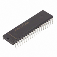
... ORDERING INFORMATION PART DS5000-32-16 DS5000-32-16+ DS5000T-32-16 DS5000T-32-16+ + Denotes a lead-free package. DS5000(T) BLOCK DIAGRAM Figure 1 MAX CRYSTAL RAM SIZE (kB) SPEED (MHz TIMEKEEPING Yes 16 Yes ...
Page 3
... PSEN also is used to invoke the bootstrap loader. At this time, PSEN is 29 PSEN pulled down externally. This should only be done once the DS5000(T) is already in a reset state. The device that pulls down should be open drain since it must not interfere with PSEN under normal operation. ...
Page 4
... The RTC is a serial device that resides in this area. A full description of the RTC access and example software is given in the Secure Microcontroller User’s Guide. If the ECE2 bit is set on a DS5000 without a timekeeper, the MOVXs will simply nonexistent memory. Software execution would not be affected otherwise. ...
Page 5
... Parallel Program Load cycles that perform the initial loading from parallel address/data information presented on the I/O port pins. This mode is timing-set compatible with the 8751H microcontroller programming mode. The DS5000(T) is placed in its Program Load configuration by simultaneously applying a logic 1 to the RST pin and forcing the PSEN will look for a parallel Program Load pulse serial ASCII carriage return (0DH) character received at 9600, 2400, 1200, or 300 bps over the serial port ...
Page 6
... Serial Program Load mode is illustrated in Figure 3. Port pins 2.7 and 2.6 must be either open or pulled high to avoid placing the DS5000( parallel load cycle. Although an 11.0592 MHz crystal is shown in Figure 3, a variety of crystal frequencies and loader baud rates are supported, shown in Table 2 ...
Page 7
... The Security Set Cycle may be used to enable and the Software Security feature of the DS5000(T). One may also enter bytes for the MCON register or for the five encryption registers using the Program MCON cycle. When using this cycle, the absolute register address must be presented at Ports 1 and the normal program cycle (Port 2 should be 00H) ...
Page 8
... Refer to the Secure Microcontroller User’s Guide for a complete description for all operational aspects of the DS5000(T). DEVELOPMENT SUPPORT The DS89C450-K00 evaluation kit (www.maxim-ic.com/DS89C450evkit) can be used to develop and test user code. It allows the user to download Intel hex-formatted code to the DS5000(T) from a PC. Refer to the Secure Microcontroller User’s Guide for more information. BAUD RATE 300 ...
Page 9
... V (Port RST, Pulldown Resistor EA Stop Mode Current Power-Fail Warning Voltage Minimum Operating Voltage Programming Supply Voltage (Parallel Program Mode) Program Supply Current Operating Current DS5000-8k @ 8MHz DS5000-32k @ 12 MHz DS5000(T)-32- MHz Idle Mode Current @ 12 MHz SYMBOL MIN V -0 2.0 IH1 V 3.5 ...
Page 10
AC CHARACTERISTICS: EXPANDED BUS MODE TIMING SPECIFICATIONS # PARAMETER 1 Oscillator Frequency 2 ALE Pulse Width 3 Address Valid to ALE Low 4 Address Hold After ALE Low 5 ALE Low to Valid Instr ALE Low to Low ...
Page 11
EXPANDED PROGRAM MEMORY READ CYCLE EXPANDED DATA MEMORY READ CYCLE ...
Page 12
EXPANDED DATA MEMORY WRITE CYCLE EXTERNAL CLOCK TIMING ...
Page 13
AC CHARACTERISTICS (cont'd) EXTERNAL CLOCK DRIVE # PARAMETER 28 External Clock High Time 29 External Clock Low Time 30 External Clock Rise Time 31 External Clock Fall Time AC CHARACTERISTICS (cont'd) SERIAL PORT TIMING - MODE 0 # PARAMETER 35 ...
Page 14
AC CHARACTERISTICS (cont'd) POWER CYCLING TIMING # PARAMETER 32 Slew Rate from V CCmin 33 Crystal Start-up Time 34 Power-on Reset Delay POWER CYCLE TIMING SYMBOL to 3. CSU t POR =0°C to 70°C; ...
Page 15
AC CHARACTERISTICS (cont'd) PARALLEL PROGRAM LOAD TIMING # PARAMETER 40 Oscillator Frequency 41 Address Setup to PROG 42 Address Hold after PROG 43 Data Setup to Low PROG 44 Data Hold after PROG 45 P2.7, 2.6, 2.5 Setup to V ...
Page 16
PARALLEL PROGRAM LOAD TIMING CAPACITANCE PARAMETER Output Capacitance Input Capacitance (test frequency=1MHz; t SYMBOL MIN TYP =25°C) A MAX UNITS NOTES ...
Page 17
... DS5000(T) TYPICAL I CC VS. FREQUENCY Normal operation is measured using: 1) External crystals on XTAL1 and 2 2) All port pins disconnected 3) RST=0 volts and EA Part performing endless loop writing to internal memory Idle mode operation is measured using: 1) External clock source at XTAL1; XTAL2 floating 2) All port pins disconnected ...
Page 18
NOTES: 1. All voltages are referenced to ground. 2. Maximum operating ns 0.5V; XTAL2 disconnected; CLKF IL 3. Idle mode I is measured with all output pins disconnected; XTAL1 driven with t CC ...
Page 19
... No circuit patent licenses are implied. Maxim/Dallas Semiconductor reserves the right to change the circuitry and specifications without notice at any time The Maxim logo is a registered trademark of Maxim Integrated Products, Inc. The Dallas logo is a registered trademark of Dallas Semiconductor Corporation. DESCRIPTION ” bullet © 2006 Maxim Integrated Products DS5000(T) ...