PIC16C63A/JW Microchip Technology, PIC16C63A/JW Datasheet - Page 95
PIC16C63A/JW
Manufacturer Part Number
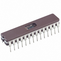
PIC16C63A/JW
Description
IC MCU EPROM 4KX14 PWM 28CDIP
Manufacturer
Microchip Technology
Series
PIC® 16Cr
Datasheets
1.PIC16C63A-04SP.pdf
(184 pages)
2.PIC16C63A-04SP.pdf
(7 pages)
3.PIC16C63A-04SP.pdf
(10 pages)
4.PIC16C63A-04SP.pdf
(10 pages)
Specifications of PIC16C63A/JW
Core Processor
PIC
Core Size
8-Bit
Speed
20MHz
Connectivity
I²C, SPI, UART/USART
Peripherals
Brown-out Detect/Reset, POR, PWM, WDT
Number Of I /o
22
Program Memory Size
7KB (4K x 14)
Program Memory Type
EPROM, UV
Ram Size
192 x 8
Voltage - Supply (vcc/vdd)
4 V ~ 5.5 V
Oscillator Type
External
Operating Temperature
0°C ~ 70°C
Package / Case
28-CDIP (0.300", 7.62mm) Window
For Use With
DVMCPA - KIT DVR BOARD EVAL SYSTEM MXDEV1
Lead Free Status / RoHS Status
Lead free / RoHS Compliant
Eeprom Size
-
Data Converters
-
Other names
PIC16C63A/JWR
PIC16C63A/JWR
PIC16C63A/JWR
Available stocks
Company
Part Number
Manufacturer
Quantity
Price


13.6
During an interrupt, only the return PC value is saved
on the stack. Users may wish to save key registers dur-
ing an interrupt i.e., W register and STATUS register.
This will have to be implemented in software.
Example 13-1 stores and restores the STATUS, W, and
PCLATH registers. The register W_TEMP must be
defined in each bank and must be defined at the same
offset from the bank base address (i.e., if W_TEMP is
defined at 0x20 in bank 0, it must also be defined at
0xA0 in bank 1).
EXAMPLE 13-1:
13.7
The Watchdog Timer is a free running on-chip RC oscil-
lator, which does not require any external components.
This RC oscillator is separate from the RC oscillator of
the OSC1/CLKIN pin. The WDT will run, even if the
clock on the OSC1/CLKIN and OSC2/CLKOUT pins of
the device has been stopped, for example, by execu-
tion of a SLEEP instruction.
During normal operation, a WDT time-out generates a
device RESET (Watchdog Timer Reset). If the device is
in SLEEP mode, a WDT time-out causes the device to
wake-up and resume normal operation (Watchdog
Timer Wake-up).
The WDT can be permanently disabled by clearing
configuration bit WDTE (Section 13.1).
2000 Microchip Technology Inc.
MOVWF
SWAPF
CLRF
MOVWF
MOVF
MOVWF
:
(ISR)
:
MOVF
MOVWF
SWAPF
MOVWF
SWAPF
SWAPF
Context Saving During Interrupts
Watchdog Timer (WDT)
W_TEMP
STATUS,W
STATUS
STATUS_TEMP
PCLATH, W
PCLATH_TEMP
PCLATH_TEMP, W
PCLATH
STATUS_TEMP, W
STATUS
W_TEMP,F
W_TEMP,W
SAVING STATUS, W, AND PCLATH REGISTERS IN RAM
;Copy W to TEMP register, could be bank one or zero
;Swap status to be saved into W
;bank 0, regardless of current bank, Clears IRP,RP1,RP0
;Save status to bank zero STATUS_TEMP register
;Only required if using pages 1, 2 and/or 3
;Save PCLATH into W
;Restore PCLATH
;Move W into PCLATH
;Swap STATUS_TEMP register into W
;(sets bank to original state)
;Move W into STATUS register
;Swap W_TEMP
;Swap W_TEMP into W
;User ISR code goes here
PIC16C63A/65B/73B/74B
The example:
a)
b)
c)
d)
e)
f)
13.7.1
The WDT has a nominal time-out period of 18 ms
(parameter #31, T
temperature, V
time-out periods are desired, a prescaler with a division
ratio of up to 1:128 can be assigned to the WDT under
software control, by writing to the OPTION register.
Time-out periods up to 128 T
The CLRWDT and SLEEP instructions clear the WDT
and the postscaler, if assigned to the WDT. In addition,
the SLEEP instruction prevents the WDT from generat-
ing a RESET, but will allow the WDT to wake the device
from SLEEP mode.
The TO bit in the STATUS register will be cleared upon
a WDT time-out.
Stores the W register.
Stores the STATUS register in bank 0.
Stores the PCLATH register.
Executes the ISR code.
Restores the STATUS register
(and bank select bit).
Restores the W and PCLATH registers.
WDT PERIOD
DD
WDT
, and process variations. If longer
). The time-out periods vary with
WDT
can be realized.
DS30605C-page 95
Related parts for PIC16C63A/JW
Image
Part Number
Description
Manufacturer
Datasheet
Request
R

Part Number:
Description:
IC MCU OTP 4KX14 PWM 28DIP
Manufacturer:
Microchip Technology
Datasheet:

Part Number:
Description:
IC MCU OTP 4KX14 PWM 28SOIC
Manufacturer:
Microchip Technology
Datasheet:
Part Number:
Description:
IC MCU OTP 4KX14 PWM 28DIP
Manufacturer:
Microchip Technology
Datasheet:
Part Number:
Description:
IC MCU OTP 4KX14 PWM 28SOIC
Manufacturer:
Microchip Technology
Datasheet:
Part Number:
Description:
IC MCU OTP 4KX14 PWM 28SOIC
Manufacturer:
Microchip Technology
Datasheet:
Part Number:
Description:
IC MCU OTP 4KX14 PWM 28DIP
Manufacturer:
Microchip Technology
Datasheet:
Part Number:
Description:
IC MCU OTP 4KX14 PWM 28SOIC
Manufacturer:
Microchip Technology
Datasheet:
Part Number:
Description:
IC MCU OTP 4KX14 PWM 28DIP
Manufacturer:
Microchip Technology
Datasheet:
Part Number:
Description:
IC MCU OTP 4KX14 PWM 28SOIC
Manufacturer:
Microchip Technology
Datasheet:
Part Number:
Description:
IC MCU OTP 4KX14 PWM 28DIP
Manufacturer:
Microchip Technology
Datasheet:
Part Number:
Description:
IC MCU OTP 4KX14 PWM 28SOIC
Manufacturer:
Microchip Technology
Datasheet:
Part Number:
Description:
IC MCU OTP 4KX14 PWM 28DIP
Manufacturer:
Microchip Technology
Datasheet:
Part Number:
Description:
IC MCU OTP 4KX14 PWM 28DIP
Manufacturer:
Microchip Technology
Datasheet:
Part Number:
Description:
IC MCU OTP 4KX14 PWM 28SOIC
Manufacturer:
Microchip Technology
Datasheet:
Part Number:
Description:
IC MCU OTP 4KX14 PWM 28DIP
Manufacturer:
Microchip Technology
Datasheet: