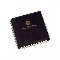
PIC16C662-20I/L Microchip Technology, PIC16C662-20I/L Datasheet - Page 129

PIC16C662-20I/L
Manufacturer Part Number
PIC16C662-20I/L
Description
IC MCU OTP 4KX14 COMP 44PLCC
Manufacturer
Microchip Technology
Series
PIC® 16Cr
Specifications of PIC16C662-20I/L
Core Processor
PIC
Core Size
8-Bit
Speed
20MHz
Peripherals
Brown-out Detect/Reset, LED, POR, WDT
Number Of I /o
33
Program Memory Size
7KB (4K x 14)
Program Memory Type
OTP
Ram Size
176 x 8
Voltage - Supply (vcc/vdd)
4 V ~ 6 V
Oscillator Type
External
Operating Temperature
-40°C ~ 85°C
Package / Case
44-PLCC
Processor Series
PIC16C
Core
PIC
Data Bus Width
8 bit
Data Ram Size
176 B
Interface Type
RS- 232
Maximum Clock Frequency
20 MHz
Number Of Programmable I/os
33
Number Of Timers
8
Operating Supply Voltage
3 V to 6 V
Maximum Operating Temperature
+ 85 C
Mounting Style
SMD/SMT
3rd Party Development Tools
52715-96, 52716-328, 52717-734
Development Tools By Supplier
ICE2000, DM163022
Minimum Operating Temperature
- 40 C
On-chip Adc
10 bit
For Use With
DVA16XL441 - ADAPTER DEVICE ICE 44PLCC309-1040 - ADAPTER 44-PLCC ZIF TO 40-DIP309-1039 - ADAPTER 44-PLCC TO 40-DIP
Lead Free Status / RoHS Status
Lead free / RoHS Compliant
Eeprom Size
-
Data Converters
-
Connectivity
-
Lead Free Status / Rohs Status
Details
Available stocks
Company
Part Number
Manufacturer
Quantity
Price
Company:
Part Number:
PIC16C662-20I/L
Manufacturer:
Microchip Technology
Quantity:
10 000
PORTE Register
Ports
Power Control/Status Register (PCON)
Power-down Mode (SLEEP)
Power-on Reset (POR)
Power-up Timer (PWRT)
Prescaler
PRO MATE Universal Programmer
Program Memory Organization
PSPMODE bit
Q
Quick-Turnaround-Production (QTP) Devices
R
RA2 pin
RC Oscillator
Reset
RETFIE Instruction
RETLW Instruction
RETURN Instruction
RLF Instruction
RRF Instruction
S
Serialized Quick-Turnaround-Production (SQTP)
SFR
SFR As Source/Destination
SLEEP Instruction
Software Simulator (MPLAB-SIM)
Special Features of the CPU
Special Function Registers
Stack
STATUS Register
SUBLW Instruction
SUBWF Instruction
SWAPF Instruction
Switching Prescalers
T
Timer Modules
Timing Diagrams and Specifications
TMR0 Interrupt
TRIS Instruction
1996 Microchip Technology Inc.
Parallel Slave Port
PORTA
PORTB
PORTC
PORTD
PORTE
Timer0
................................................................................... 74
................................................................................. 27
................................................................................ 59
............................................................................. 30
Devices
Block Diagram
Counter Mode
External Clock
Interrupt
Prescaler
Section
Timer Mode
Timing Diagram
TMR0 register
.......................................................................... 44
..................................................................... 29
..................................................................... 32
..................................................................... 34
..................................................................... 14
..................................................................... 14
................................................................... 58
........................................................... 35, 36
................................................................ 83
................................................................ 67
............................................................... 83
.............................................................. 85
............................................................. 36
............................................................. 41
.............................................................. 7
............................................................ 41
........................................................... 21
.......................................................... 83
.......................................................... 44
......................................................... 82
......................................................... 82
......................................................... 84
......................................................... 84
......................................................... 85
...................................................... 83
..................................................... 45
..................................................... 41
.................................................. 39
................................................. 60
................................................. 41
................................................. 41
................................................. 43
................................................. 41
............................................... 60
.............................................. 41
..................................... 19, 74
.......................................... 74
........................................ 70
........................................ 55
.................................... 17
............................... 89
.......................... 87
.......................... 98
..................... 61
............ 7
Preliminary
PIC16C64X & PIC16C66X
TRISA
TRISB
TRISC Register
TRISD Register
TRISE Register
V
Voltage Reference Module
VRCON Register
W
Watchdog Timer (WDT)
X
XORLW Instruction
XORWF Instruction
LIST OF EXAMPLES
Example 3-1:Instruction Pipeline Flow ............................... 15
Example 4-1:Indirect Addressing........................................ 28
Example 5-1:Initializing PORTA ......................................... 29
Example 5-2:Initializing PORTC ......................................... 34
Example 5-3:Read-Modify-Write Instructions on an
Example 6-1:Changing Prescaler (Timer0 WDT)............. 45
Example 6-2:Changing Prescaler (WDT Timer0)............. 45
Example 7-1:Initializing Comparator Module...................... 49
Example 8-1:Voltage Reference Configuration .................. 54
Example 9-1:Saving the STATUS and W Registers in
LIST OF FIGURES
Figure 3-1: PIC16C641/642 Block Diagram..................... 10
Figure 3-2: PIC16C661/662 Block Diagram..................... 11
Figure 3-3: Clock/Instruction Cycle .................................. 15
Figure 4-1: PIC16C641/661 Program Memory Map and
Figure 4-2: PIC16C642/662 Program Memory Map and
Figure 4-3: PIC16C641/661 Data Memory Map .............. 18
Figure 4-4: PIC16C642/662 Data Memory Map .............. 19
Figure 4-5: STATUS Register (Address 03h, 83h) .......... 21
Figure 4-6: OPTION Register (address 81h) ................... 22
Figure 4-7: INTCON Register (address 0Bh, 8Bh) .......... 23
Figure 4-8: PIE1 Register (address 8Ch)......................... 24
Figure 4-9: PIR1 Register (address 0Ch) ........................ 25
Figure 4-10: PCON Register (Address 8Eh)...................... 26
Figure 4-11: Loading Of PC In Different Situations............ 27
Figure 4-12: Direct/indirect Addressing.............................. 28
Figure 5-1: Block Diagram of RA1:RA0 Pins ................... 29
Figure 5-2: Block Diagram of RA2 Pin ............................. 30
Figure 5-3: Block Diagram of RA3 Pin ............................. 30
Figure 5-4: Block Diagram of RA4 Pin ............................. 31
Figure 5-5: Block Diagram of RB7:RB4 Pins ................... 32
Figure 5-6: Block Diagram of RB3:RB0 Pins ................... 32
Figure 5-7: PORTC Block Diagram (in I/O port Mode) .... 34
Figure 5-8: PORTD Block Diagram (in I/O Port Mode) .... 35
Figure 5-9: TRISE Register (Address 89h) ...................... 36
Figure 5-10: PORTE Block Diagram (in I/O Port Mode) .... 37
Figure 5-11: Successive I/O Operation.............................. 38
Figure 5-12: PORTD and PORTE as a Parallel Slave Port 39
Figure 6-1: Timer0 Block Diagram ................................... 41
Figure 6-2: Timer0 Timing: Internal Clock/No Prescaler.. 41
Figure 6-3: Timer0 Timing: Internal Clock/Prescale 1:2... 42
............................................................................... 29
............................................................................... 32
I/O Port .......................................................... 38
RAM............................................................... 68
Stack.............................................................. 17
Stack.............................................................. 17
............................................................... 36
.............................................................. 34
.............................................................. 35
............................................................ 53
........................................................ 85
........................................................ 85
................................................ 69
........................................... 53
DS30559A-page 129


