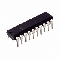
PIC16F639-E/P Microchip Technology, PIC16F639-E/P Datasheet - Page 2

PIC16F639-E/P
Manufacturer Part Number
PIC16F639-E/P
Description
IC MCU FLASH 2KX14 20DIP
Manufacturer
Microchip Technology
Series
PIC® 16Fr
Datasheets
1.PIC16F616T-ISL.pdf
(8 pages)
2.PIC12F635-ISN.pdf
(234 pages)
3.PIC16F636-ISL.pdf
(8 pages)
4.PIC16F636-ISL.pdf
(4 pages)
5.PIC16F639-ISS.pdf
(6 pages)
Specifications of PIC16F639-E/P
Core Processor
PIC
Core Size
8-Bit
Speed
20MHz
Peripherals
Brown-out Detect/Reset, LVD, POR, WDT
Number Of I /o
11
Program Memory Size
3.5KB (2K x 14)
Program Memory Type
FLASH
Ram Size
128 x 8
Voltage - Supply (vcc/vdd)
2 V ~ 3.6 V
Oscillator Type
Internal
Operating Temperature
-40°C ~ 125°C
Package / Case
20-DIP (0.300", 7.62mm)
For Use With
AC162066 - HEADER INTRFC MPLAB ICD2 20PINAC164039 - MODULE SKT PROMATE II 20DIP/SOICDM163029 - BOARD PICDEM FOR MECHATRONICSACICE0203 - MPLABICE 20P 300 MIL ADAPTER
Lead Free Status / RoHS Status
Lead free / RoHS Compliant
Eeprom Size
-
Data Converters
-
Connectivity
-
TB088
TABLE 1:
DS91088B-page 2
Parameters/Features
Supply Voltage
LF Input Sensitivity
LF Input Wake-up Pattern
Eight Configuration AFE Registers
Selectable AFE Output
LF Input Channel Selection
LF Input Modulation Depth Selection
Antenna Tuning Capacitance
Input Sensitivity Reductions
Sleep Current
Standby Current
Active Current
Base Station Data Rate to Transponder 10 Kbps (max) with NRZ Format
MCU Memory
MCU I/O Pins
Selectable MCU Internal Clock
Encryption/Decryption
Interrupt-on-Change of PORTA (IOCA) Each of the PORTA pins is individually configured as an interrupt-on-change
Programmable Low-Voltage Detector
(PLVD)
Two Analog Comparators
Two Internal Timers (Timer0, Timer1)
Operating Temperature
Note:
Refer to the “ PIC12F635/PIC16F636/639 Data Sheet ” (DS41232) for more detail.
DEVICE FEATURES
Description
2.0-3.6V
1-6 mV
Programmable: High and low pulse durations (8 different timing choices)
Programmable via a modified SPI, except STATUS register (read-only)
Demodulated Data, RSSI Current, Carrier Clock
Each channel can be individually enabled or disabled
8%, 14%, 33%, 60%
Programmable up to 63 pF (1 pF/step) for each channel
Programmable up to 30 dB (2 dB/step) for each channel
200 nA typical for both MCU and analog front-end
1 channel enabled: 2 A, V
2 channels enabled: 3 A, V
3 channels enabled: 4 A, V
MCU: 500 A @ V
AFE: 13 A (3 channels enabled)
Program Flash Memory: 2048 Words
EEPROM: 256 Bytes
SRAM: 128 Bytes
12 I/O, 3 I/O are shared with AFE
31 kHz, 125 kHz, 250 kHz, 500 kHz, 1 MHz, 2 MHz, 4 MHz, 8 MHz
K
pin
This feature can be used to detect V
These comparators are general purpose. One can be used when
implementing firmware-based ADC for RSSI output.
These timers are useful for measuring pulse timing. The Timer1 can also be
used for firmware-based ADC implementation.
-40 C to 85 C
EE
L
OQ
PP
®
hardware peripheral in microcontroller
DD
= 3.0V and F
DD
DD
DD
= 3.0V and MCU = Sleep condition
= 3.0V and MCU = Sleep condition
= 3.0V and MCU = Sleep condition
OSC
DD
= 4 MHz
(battery voltage) level
© 2005 Microchip Technology Inc.


