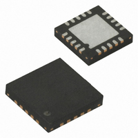
ATTINY44-20MU Atmel, ATTINY44-20MU Datasheet - Page 89

ATTINY44-20MU
Manufacturer Part Number
ATTINY44-20MU
Description
IC MCU AVR 4K FLASH 20MHZ 20-QFN
Manufacturer
Atmel
Series
AVR® ATtinyr
Specifications of ATTINY44-20MU
Core Processor
AVR
Core Size
8-Bit
Speed
20MHz
Connectivity
USI
Peripherals
Brown-out Detect/Reset, POR, PWM, WDT
Number Of I /o
12
Program Memory Size
4KB (2K x 16)
Program Memory Type
FLASH
Eeprom Size
256 x 8
Ram Size
256 x 8
Voltage - Supply (vcc/vdd)
2.7 V ~ 5.5 V
Data Converters
A/D 8x10b
Oscillator Type
Internal
Operating Temperature
-40°C ~ 85°C
Package / Case
20-MLF®, QFN
Data Bus Width
8 bit
Data Ram Size
256 B
Interface Type
SPI
Maximum Clock Frequency
20 MHz
Number Of Programmable I/os
12
Number Of Timers
2
Maximum Operating Temperature
+ 85 C
Mounting Style
SMD/SMT
Minimum Operating Temperature
- 40 C
On-chip Adc
10 bit, 8 Channel
For Use With
ATAVRISP2 - PROGRAMMER AVR IN SYSTEM
Lead Free Status / RoHS Status
Lead free / RoHS Compliant
Available stocks
Company
Part Number
Manufacturer
Quantity
Price
Company:
Part Number:
ATTINY44-20MUR
Manufacturer:
ATMEL
Quantity:
2 100
- Current page: 89 of 238
- Download datasheet (5Mb)
12.2.3
12.3
12.4
8006K–AVR–10/10
Timer/Counter Clock Sources
Counter Unit
Compatibility
The 16-bit Timer/Counter has been updated and improved from previous versions of 16-bit AVR
Timer/Counters. This 16-bit Timer/Counter is fully compatible with the earlier version regarding:
The following control bits have changed name, but have same functionality and register location:
The following bits are added to the 16-bit Timer/Counter Control Registers:
The 16-bit Timer/Counter has improvements that will affect backward compatibility in some spe-
cial cases.
The Timer/Counter can be clocked by an internal or an external clock source. The clock source
is selected by the Clock Select logic which is controlled by the Clock Select (CS12:0) bits
located in the Timer/Counter control Register B (TCCR1B). For details on clock sources and
prescaler, see
The main part of the 16-bit Timer/Counter is the programmable 16-bit bi-directional counter unit.
Figure 12-2 on page 89
Figure 12-2. Counter Unit Block Diagram
• All 16-bit Timer/Counter related I/O Register address locations, including Timer Interrupt
• Bit locations inside all 16-bit Timer/Counter Registers, including Timer Interrupt Registers.
• Interrupt Vectors.
• PWM10 is changed to WGM10.
• PWM11 is changed to WGM11.
• CTC1 is changed to WGM12.
• 1A and 1B are added to TCCR1A.
• WGM13 is added to TCCR1B.
Registers.
TCNTnH (8-bit)
TEMP (8-bit)
TCNTn (16-bit Counter)
DATA BUS
“Timer/Counter Prescaler” on page
TCNTnL (8-bit)
shows a block diagram of the counter and its surroundings.
(8-bit)
Direction
Count
Clear
Control Logic
TOP
115.
BOTTOM
TOVn
(Int.Req.)
clk
Tn
ATtiny24/44/84
Clock Select
( From Prescaler )
Detector
Edge
Tn
89
Related parts for ATTINY44-20MU
Image
Part Number
Description
Manufacturer
Datasheet
Request
R

Part Number:
Description:
Manufacturer:
Atmel Corporation
Datasheet:

Part Number:
Description:
Manufacturer:
Atmel Corporation
Datasheet:

Part Number:
Description:
MCU AVR 4K FLASH 15MHZ 20-QFN
Manufacturer:
Atmel
Datasheet:

Part Number:
Description:
IC MCU AVR 4K FLASH 20MHZ 14SOIC
Manufacturer:
Atmel
Datasheet:

Part Number:
Description:
MCU AVR 4KB FLASH 20MHZ 14SOIC
Manufacturer:
Atmel
Datasheet:

Part Number:
Description:
MCU AVR 4KB FLASH 20MHZ 20QFN
Manufacturer:
Atmel
Datasheet:

Part Number:
Description:
IC MCU AVR 4K FLASH 15MHZ 14SOIC
Manufacturer:
Atmel
Datasheet:

Part Number:
Description:
IC MCU AVR 4K FLASH 20MHZ 14-DIP
Manufacturer:
Atmel
Datasheet:

Part Number:
Description:
Manufacturer:
Atmel Corporation
Datasheet:

Part Number:
Description:
Microcontrollers (MCU) 512B FL 32B SRAM TIMER ATTINY4 12MHz
Manufacturer:
Atmel

Part Number:
Description:
IC MCU AVR 512B FLASH SOT-23-6
Manufacturer:
Atmel
Datasheet:

Part Number:
Description:
IC MCU AVR 512B FLASH SOT-23-6
Manufacturer:
Atmel
Datasheet:


