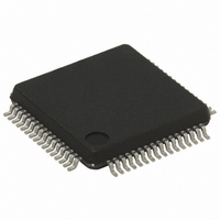
ST7FMC2R7T6TR STMicroelectronics, ST7FMC2R7T6TR Datasheet - Page 238

ST7FMC2R7T6TR
Manufacturer Part Number
ST7FMC2R7T6TR
Description
IC MCU 8BIT 32K FLASH 64-LQFP
Manufacturer
STMicroelectronics
Series
ST7r
Datasheet
1.ST7FMC2S4T6.pdf
(309 pages)
Specifications of ST7FMC2R7T6TR
Core Processor
ST7
Core Size
8-Bit
Speed
8MHz
Connectivity
LINSCI, SPI
Peripherals
LVD, Motor Control PWM, POR, PWM, WDT
Number Of I /o
44
Program Memory Size
48KB (48K x 8)
Program Memory Type
FLASH
Ram Size
1.5K x 8
Voltage - Supply (vcc/vdd)
3.8 V ~ 5.5 V
Data Converters
A/D 16x10b
Oscillator Type
Internal
Operating Temperature
-40°C ~ 85°C
Package / Case
64-LQFP
For Use With
497-8402 - BOARD EVAL COMPLETE INVERTER497-8400 - KIT IGBT PWR MODULE CTRL ST7MC497-6408 - BOARD EVAL BLDC SENSORLESS MOTOR497-4734 - EVAL KIT 3KW POWER DRIVER BOARD497-4733 - EVAL KIT 1KW POWER DRIVER BOARD497-4732 - EVAL KIT 300W POWER DRIVER BOARD497-4731 - EVAL KIT PWR DRIVER CONTROL BRD
Lead Free Status / RoHS Status
Lead free / RoHS Compliant
Eeprom Size
-
Available stocks
Company
Part Number
Manufacturer
Quantity
Price
Company:
Part Number:
ST7FMC2R7T6TR
Manufacturer:
STMicroelectronics
Quantity:
10 000
- Current page: 238 of 309
- Download datasheet (6Mb)
ST7MC1xx/ST7MC2xx
10-BIT A/D CONVERTER (ADC) (Cont’d)
When a conversion is complete:
To read the 10 bits, perform the following steps:
1. Poll the EOC bit or wait for EOC interrupt
2. Read ADCDRLSB
3. Read ADCDRMSB
The EOC bit is reset by hardware once the AD-
CDRMSB is read.
To read only 8 bits, perform the following steps:
1. Poll the EOC bit or wait for EOC interrupt
2. Read ADCDRMSB
The EOC bit is reset by hardware once the AD-
CDRMSB is read.
Changing the conversion channel
The application can change channels during con-
version. In this case the current conversion is
stopped and the A/D converter starts converting
the newly selected channel.
ADCCR consistency
If an End Of Conversion event occurs after soft-
ware has read the ADCDRLSB but before it has
read the ADCDRMSB, there would be a risk that
the two values read would belong to different sam-
ples.
238/309
– The EOC bit is set by hardware
– An interrupt request is generated if the ADCIE
– The result is in the ADCDR registers and re-
bit in the MCCBCR register is set (see
6.4.7 on page
mains valid until the next conversion has end-
ed.
38).
section
To guarantee consistency:
Thus, it is mandatory to read the ADCDRMSB just
after reading the ADCDRLSB. Otherwise the AD-
CDR register will not be updated until the AD-
CDRMSB is read.
10.8.4 Low Power Modes
Note: The A/D converter may be disabled by re-
setting the ADON bit. This feature allows reduced
power consumption when no conversion is need-
ed.
10.8.5 Interrupts
1)
section 6.4.7 on page
Mode
Wait
Halt
End of Conver-
sion
The ADCIE bit is in the MCCBCR register (see
– The ADCDRMSB and the ADCDRLSB are
– The ADCDRMSB and the ADCDRLSB are un-
Interrupt
locked when the ADCCRLSB is read
locked when the MSB is read or when ADON
is reset.
Event
Description
No effect on A/D Converter
A/D Converter disabled.
After wake up from Halt mode, the A/D
Converter requires a stabilization time
t
before accurate conversions can be
performed.
STAB
Event
EOC
Flag
(see Electrical Characteristics)
38)
ADCIE
Control
Enable
Bit
1)
from
Wait
Exit
Yes
from
Exit
Halt
No
Related parts for ST7FMC2R7T6TR
Image
Part Number
Description
Manufacturer
Datasheet
Request
R

Part Number:
Description:
STMicroelectronics [RIPPLE-CARRY BINARY COUNTER/DIVIDERS]
Manufacturer:
STMicroelectronics
Datasheet:

Part Number:
Description:
STMicroelectronics [LIQUID-CRYSTAL DISPLAY DRIVERS]
Manufacturer:
STMicroelectronics
Datasheet:

Part Number:
Description:
BOARD EVAL FOR MEMS SENSORS
Manufacturer:
STMicroelectronics
Datasheet:

Part Number:
Description:
NPN TRANSISTOR POWER MODULE
Manufacturer:
STMicroelectronics
Datasheet:

Part Number:
Description:
TURBOSWITCH ULTRA-FAST HIGH VOLTAGE DIODE
Manufacturer:
STMicroelectronics
Datasheet:

Part Number:
Description:
Manufacturer:
STMicroelectronics
Datasheet:

Part Number:
Description:
DIODE / SCR MODULE
Manufacturer:
STMicroelectronics
Datasheet:

Part Number:
Description:
DIODE / SCR MODULE
Manufacturer:
STMicroelectronics
Datasheet:

Part Number:
Description:
Search -----> STE16N100
Manufacturer:
STMicroelectronics
Datasheet:

Part Number:
Description:
Search ---> STE53NA50
Manufacturer:
STMicroelectronics
Datasheet:

Part Number:
Description:
NPN Transistor Power Module
Manufacturer:
STMicroelectronics
Datasheet:

Part Number:
Description:
DIODE / SCR MODULE
Manufacturer:
STMicroelectronics
Datasheet:


