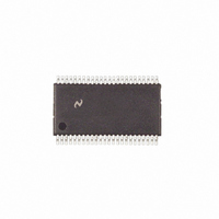
COP8SBR9IMT8 National Semiconductor, COP8SBR9IMT8 Datasheet - Page 31

COP8SBR9IMT8
Manufacturer Part Number
COP8SBR9IMT8
Description
IC MCU EEPROM 8BIT 32K 48-TSSOP
Manufacturer
National Semiconductor
Series
COP8™ 8Sr
Datasheet
1.COP8SCR9HVA8NOPB.pdf
(80 pages)
Specifications of COP8SBR9IMT8
Core Processor
COP8
Core Size
8-Bit
Speed
20MHz
Connectivity
Microwire/Plus (SPI), UART/USART
Peripherals
Brown-out Detect/Reset, POR, PWM, WDT
Number Of I /o
39
Program Memory Size
32KB (32K x 8)
Program Memory Type
FLASH
Ram Size
1K x 8
Voltage - Supply (vcc/vdd)
2.7 V ~ 5.5 V
Oscillator Type
Internal
Operating Temperature
-40°C ~ 85°C
Package / Case
48-TSSOP
Lead Free Status / RoHS Status
Contains lead / RoHS non-compliant
Eeprom Size
-
Data Converters
-
Other names
*COP8SBR9IMT8
cpgerase
cmserase
creadbf
cblockr
cwritebf
cblockw
exit
Command/
11.0 In-System Programming
The following table lists the User ISP/Virtual E
required parameters and return data, if applicable. The com-
• Copy a block of data from RAM into flash program
• Copy a block of data from program flash memory to RAM.
(Continued)
Label
memory.
Page Erase
Mass Erase
Read Byte
Block Read
Write Byte
Block Write
EXIT
Function
Entry Point
Command
0x1A
0x17
0x26
0x14
0x23
0x62
0x11
TABLE 11. User ISP/Virtual E
Register ISPADHI is loaded by the user
with the high byte of the address.
Register ISPADLO is loaded by the
user with the low byte of the address.
Accumulator A contains the
confirmation key 0x55.
Register ISPADHI is loaded by the user
with the high byte of the address.
Register ISPADLO is loaded by the
user with the low byte of the address.
Register ISPADHI is loaded by the user
with the high byte of the address.
Register ISPADLO is loaded by the
user with the low byte of the address.
X pointer contains the beginning RAM
address where the result(s) will be
returned.
Register BYTECOUNTLO contains the
number of n bytes to read
(0 ≤ n ≤ 255). It is up to the user to
setup the segment register.
Register ISPADHI is loaded by the user
with the high byte of the address.
Register ISPADLO is loaded by the
user with the low byte of the address.
Register ISPWR contains the Data
Byte to be written.
Register ISPADHI is loaded by the user
with the high byte of the address.
Register ISPADLO is loaded by the
user with the low byte of the address.
Register BYTECOUNTLO contains the
number of n bytes to write (0 ≤ n ≤ 16).
The combination of the
BYTECOUNTLO and the ISPADLO
registers must be set such that the
operation will not cross a 64 byte
boundary.
X pointer contains the beginning RAM
address of the data to be written.
It is up to the user to setup the
segment register.
N/A
2
commands,
Parameters
31
mand entry point is used as an argument to the JSRB
instruction. Table 12 lists the Ram locations and Peripheral
Registers, used for User ISP and Virtual E
pected contents. Please refer to the COP8 FLASH ISP User
Manual for additional information and programming ex-
amples on the use of User ISP and Virtual E
2
Entry Points
N/A (A page of memory beginning at
ISPADHI, ISPADLO will be erased)
N/A (The entire Flash Memory will be
erased)
Data Byte in Register ISPRD.
n Data Bytes, Data will be returned
beginning at a location pointed to by
the RAM address in X.
N/A
N/A
N/A (Device will Reset)
Return Data
2
, and their ex-
2
.
www.national.com


