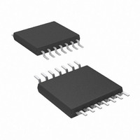
LMV324TSG-13 Diodes Inc, LMV324TSG-13 Datasheet - Page 5

LMV324TSG-13
Manufacturer Part Number
LMV324TSG-13
Description
IC OPAMP R-R QUAD 1MHZ 14TSSOP
Manufacturer
Diodes Inc
Datasheet
1.LMV321SEG-7.pdf
(16 pages)
Specifications of LMV324TSG-13
Amplifier Type
General Purpose
Number Of Circuits
4
Output Type
Rail-to-Rail
Slew Rate
1 V/µs
Gain Bandwidth Product
1MHz
Current - Input Bias
15nA
Voltage - Input Offset
1700µV
Current - Supply
340µA
Current - Output / Channel
90mA
Voltage - Supply, Single/dual (±)
2.7 V ~ 5.5 V
Operating Temperature
-40°C ~ 85°C
Mounting Type
Surface Mount
Package / Case
14-TSSOP
Number Of Channels
Quad
Common Mode Rejection Ratio (min)
50 dB
Input Voltage Range (max)
5.5 V
Input Voltage Range (min)
2.7 V
Input Offset Voltage
1.7 mV
Input Bias Current (max)
10 nA
Supply Current
340 uA
Maximum Operating Temperature
+ 85 C
Minimum Operating Temperature
- 40 C
Mounting Style
SMD/SMT
Operating Temperature Range
- 40 C to + 85 C
Supply Voltage (max)
5.5 V
Supply Voltage (min)
2.7 V
Lead Free Status / RoHS Status
Lead free / RoHS Compliant
-3db Bandwidth
-
Lead Free Status / Rohs Status
Lead free / RoHS Compliant
Other names
LMV324TSG-13DITR
Available stocks
Company
Part Number
Manufacturer
Quantity
Price
Part Number:
LMV324TSG-13
Manufacturer:
DIDOES
Quantity:
20 000
Electrical Characteristics
Notes:
LMV321/358/324
Document number: DS33196 Rev. 6 - 2
5V AC Electrical Characteristics
Unless otherwise specified, all limits guaranteed for T
Boldface limits apply at the temperature extremes.
GBWP Gain-Bandwidth Product
SR
Φ
G
e
m
m
n
5. Typical values represent the most likely parametric norm as determined at the time of characterization. Actual typical values may vary over time
6. All limits are guaranteed by testing or statistical analysis.
7. R
8. All numbers are typical, and apply for packages soldered directly onto a PC board in still air.
9. Connected as voltage follower with 3V step input. Number specified is the slower of the positive and negative slew rates.
Slew Rate
Phase Margin
Gain Margin
Input-Referred Voltage Noise
and will also depend on the application and configuration. The typical values are not tested and are not guaranteed on shipped production material.
L
is connected to V-. The output voltage is 0.5V ≤ V
(Continued)
(Note 9)
C
f > 50 kHz
L
= 200 pF
GENERAL PURPOSE, LOW VOLTAGE, RAIL-TO-RAIL
A
= 25°C, V
O
≤ 4.5V.
www.diodes.com
+
= 5V, V
5 of 16
LMV321/LMV358/LMV324
-
= 0V, V
OUTPUT OPERATIONAL AMPLIFIERS
CM
= 2.0V, VO = V
+
/2 and R
60
10
23
1
1
L
> 1 MΩ.
© Diodes Incorporated
February 2011
MHz
V/µs
Deg
dB
nV
H
Z


