LM2904N Fairchild Semiconductor, LM2904N Datasheet - Page 8
LM2904N
Manufacturer Part Number
LM2904N
Description
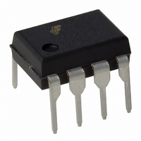
IC OPAMP DUAL -40-85 C 8-DIP
Manufacturer
Fairchild Semiconductor
Datasheet
1.LM358MX.pdf
(12 pages)
Specifications of LM2904N
Amplifier Type
General Purpose
Number Of Circuits
2
Slew Rate
0.3 V/µs
Current - Input Bias
45nA
Voltage - Input Offset
2900µV
Current - Supply
800µA
Current - Output / Channel
30mA
Voltage - Supply, Single/dual (±)
3 V ~ 26 V, ±1.5 V ~ 13 V
Operating Temperature
-40°C ~ 85°C
Mounting Type
Through Hole
Package / Case
8-DIP (0.300", 7.62mm)
Number Of Channels
2
Common Mode Rejection Ratio (min)
50 dB
Input Offset Voltage
7 mV
Input Bias Current (max)
250 nA
Operating Supply Voltage
5 V, 9 V, 12 V, 15 V
Supply Current
1.2 mA
Maximum Operating Temperature
+ 85 C
Minimum Operating Temperature
- 40 C
Dual Supply Voltage
+/- 3 V, +/- 5 V, +/- 9 V, +/- 12 V
Maximum Dual Supply Voltage
+/- 13 V
Minimum Dual Supply Voltage
+/- 1.5 V
Mounting Style
Through Hole
Shutdown
No
Supply Voltage (max)
26 V
Supply Voltage (min)
3 V
Technology
Bipolar
Voltage Gain Db
100 dB
Lead Free Status / RoHS Status
Lead free / RoHS Compliant
Output Type
-
-3db Bandwidth
-
Gain Bandwidth Product
-
Lead Free Status / Rohs Status
Lead free / RoHS Compliant
Other names
LM2904NFS
Available stocks
Company
Part Number
Manufacturer
Quantity
Price

Part Number:
LM2904N
Manufacturer:
ON/ه®‰و£®ç¾ژ
Quantity:
20 000
Company:
Part Number:
LM2904N/NOPB
Manufacturer:
National Semiconductor
Quantity:
1 972
Company:
Part Number:
LM2904NG
Manufacturer:
ON Semiconductor
Quantity:
8 700
Part Number:
LM2904NG
Manufacturer:
ON/ه®‰و£®ç¾ژ
Quantity:
20 000
Company:
Part Number:
LM2904N_NOPB
Manufacturer:
NS
Quantity:
319


LM2904,LM358/LM358A,LM258/LM258A
Typical Performance Characteristics
(Continued)
Figure 7. Input Voltage Range vs Supply Voltage
Figure 8. Common-Mode Rejection Ratio
Figure 9. Output Current vs Temperature (Current Limiting)
Figure 10. Input Current vs Temperature
Figure 11. Voltage Follower Pulse Response
Figure 12. Voltage Follower Pulse Response
(Small Signal)
8
Related parts for LM2904N
Image
Part Number
Description
Manufacturer
Datasheet
Request
R

Part Number:
Description:
Fairchild Semiconductor [IGBT MODULE]
Manufacturer:
Fairchild Semiconductor
Datasheet:

Part Number:
Description:
Discrete Semiconductor Modules
Manufacturer:
Fairchild Semiconductor
Part Number:
Description:
Discrete Semiconductor Modules
Manufacturer:
Fairchild Semiconductor
Part Number:
Description:
This N-Channel MOSFET is produced using Fairchild Semiconductor’s advanced Power Trench® process
Manufacturer:
Fairchild Semiconductor
Datasheet:
Part Number:
Description:
This N-Channel MOSFET is produced using Fairchild Semiconductor’s advanced Power Trench® process
Manufacturer:
Fairchild Semiconductor
Datasheet:
Part Number:
Description:
This N-Channel MOSFET is produced using Fairchild Semiconductor’s advanced PowerTrench® process
Manufacturer:
Fairchild Semiconductor
Datasheet:
Part Number:
Description:
This N-Channel MOSFET is produced using Fairchild Semiconductor’s advanced PowerTrench® process
Manufacturer:
Fairchild Semiconductor
Datasheet:
Part Number:
Description:
This N-Channel MOSFET is produced using Fairchild Semiconductor’s advanced Power Trench® process
Manufacturer:
Fairchild Semiconductor
Datasheet:
Part Number:
Description:
This N-Channel logic Level MOSFETs are produced using Fairchild Semiconductor‘s advanced Power Trench® process that has been special tailored to minimize the on-state resistance and yet maintain superior switching performance
Manufacturer:
Fairchild Semiconductor
Datasheet:
Part Number:
Description:
This N-Channel MOSFET is produced using Fairchild Semiconductor’s advanced Power Trench® process
Manufacturer:
Fairchild Semiconductor
Datasheet:
Part Number:
Description:
This N-Channel SyncFET™ is produced using Fairchild Semiconductor’s advanced PowerTrench® process
Manufacturer:
Fairchild Semiconductor
Datasheet:
Part Number:
Description:
This N-Channel SyncFET™ is produced using Fairchild Semiconductor’s advanced PowerTrench® process
Manufacturer:
Fairchild Semiconductor
Datasheet:
Part Number:
Description:
This N-Channel SyncFET™ is produced using Fairchild Semiconductor’s advanced PowerTrench® process
Manufacturer:
Fairchild Semiconductor
Datasheet:
Part Number:
Description:
This N-Channel logic Level MOSFETs are produced using Fairchild Semiconductor‘s advanced Power Trench® process that has been special tailored to minimize the on-state resistance and yet maintain superior switching performance
Manufacturer:
Fairchild Semiconductor
Datasheet:
Part Number:
Description:
This N-Channel MOSFET is produced using Fairchild Semiconductor’s advanced Power Trench® process that has been especially tailored to minimize the on-state resistance and yet maintain superior switching performance
Manufacturer:
Fairchild Semiconductor
Datasheet: