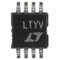
LTC1992-2CMS8#PBF Linear Technology, LTC1992-2CMS8#PBF Datasheet - Page 37

LTC1992-2CMS8#PBF
Manufacturer Part Number
LTC1992-2CMS8#PBF
Description
IC AMP/DVR I/O GAIN OF 2 8MSOP
Manufacturer
Linear Technology
Datasheet
1.LTC1992CMS8PBF.pdf
(42 pages)
Specifications of LTC1992-2CMS8#PBF
Amplifier Type
Differential
Number Of Circuits
1
Output Type
Differential, Rail-to-Rail
Slew Rate
1.5 V/µs
Gain Bandwidth Product
3.2MHz
Current - Input Bias
2pA
Voltage - Input Offset
250µV
Current - Supply
700µA
Current - Output / Channel
30mA
Voltage - Supply, Single/dual (±)
2.7 V ~ 11 V, ±1.35 V ~ 5.5 V
Operating Temperature
0°C ~ 70°C
Mounting Type
Surface Mount
Package / Case
8-MSOP, Micro8™, 8-uMAX, 8-uSOP,
No. Of Amplifiers
1
Input Offset Voltage
2.5mV
Bandwidth
4GHz
Supply Voltage Range
2.7V To 11V
Supply Current
800µA
Amplifier Case Style
MSOP
No. Of Pins
8
Rohs Compliant
Yes
Lead Free Status / RoHS Status
Lead free / RoHS Compliant
-3db Bandwidth
-
Available stocks
Company
Part Number
Manufacturer
Quantity
Price
applicaTions inForMaTion
once the V
same as a standard noninverting op amp circuit multiplied
by two to account for the complementary output. Taking
R
as the top circuit. As in the top circuit, this circuit is also
useful as a single-ended output, high input impedance
inverting gain block (this time with gain). The input com-
mon mode considerations are similar to the top circuit’s,
but are not nearly as constrained since there is now gain
in the noninverting amplifier path. This circuit, with V
at ground, also permits a rail-to-rail output swing in most
applications.
FB
to zero (i.e., taking β to one) gives the same formula
OCM
Figure 7. Asymmetrical Feedback Application Circuits (Most Suitable in Applications with Dual,
Split Supplies (e.g., ±5V), Ground Referenced Single-Ended Input Signals and V
voltage is set to zero, the gain formula is the
V
OCM
V
IN
V
V
OCM
OCM
V
V
R
R
IN
IN
IN
IN
R
FB
–
V
+
–
V
+
–
V
+
OCM
OCM
OCM
R
FB
+
–
+
–
+
–
LTC1992
LTC1992
LTC1992
1992 F07
+V
+V
+V
–V
–V
–V
OCM
OUT
OUT
OUT
OUT
OUT
OUT
V
SETTING V
V
V
SETTING V
V
V
SETTING V
V
The bottom circuit is another circuit that utilizes a standard
op amp configuration with a complementary output. In this
case, the standard op amp circuit has an inverting con-
figuration. With V
same as a standard inverting op amp circuit multiplied by
two to account for the complementary output. This circuit
does not have any common mode level constraints as the
inverting input voltage sets the input common mode level.
This circuit also delivers rail-to-rail output voltage swing
without any concerns.
OUTDIFF
OUTDIFF
OUTDIFF
OUTDIFF
OUTDIFF
OUTDIFF
= 2(+V
= 2V
= 2
= 2V
= 2
= 2V
OCM
OCM
OCM
(
(
IN
IN
IN
+V
+V
= 0V
= 0V
= 0V
IN
( )
( )
IN
IN
1 –
1
– V
1
1 –
= 2V
OCM
– V
= 2V
OCM
IN
+ V
)
(
IN
1 +
OCM
OCM
)
( )
R
R
R
R
FB
; =
IN
)
FB
IN
OCM
at zero volts, the gain formula is the
)
; =
R
IN
LTC1992 Family
R
Connected to Ground)
R
+ R
IN
IN
R
FB
+ R
IN
FB
1992fa


