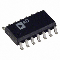
OP747ARZ Analog Devices Inc, OP747ARZ Datasheet - Page 12

OP747ARZ
Manufacturer Part Number
OP747ARZ
Description
IC OPAMP GP R-R 700KHZ 14SOIC
Manufacturer
Analog Devices Inc
Datasheet
1.OP777ARMZ-REEL.pdf
(16 pages)
Specifications of OP747ARZ
Slew Rate
0.2 V/µs
Amplifier Type
General Purpose
Number Of Circuits
4
Output Type
Rail-to-Rail
Gain Bandwidth Product
700kHz
Current - Input Bias
5nA
Voltage - Input Offset
30µV
Current - Supply
320µA
Current - Output / Channel
30mA
Voltage - Supply, Single/dual (±)
2.7 V ~ 30 V, ±1.35 V ~ 15 V
Operating Temperature
-40°C ~ 85°C
Mounting Type
Surface Mount
Package / Case
14-SOIC (3.9mm Width), 14-SOL
Op Amp Type
Low Power
No. Of Amplifiers
4
Bandwidth
700kHz
Supply Voltage Range
2.7V To 30V
Amplifier Case Style
SOIC
No. Of Pins
14
Lead Free Status / RoHS Status
Lead free / RoHS Compliant
-3db Bandwidth
-
Lead Free Status / RoHS Status
Lead free / RoHS Compliant, Lead free / RoHS Compliant
Available stocks
Company
Part Number
Manufacturer
Quantity
Price
Part Number:
OP747ARZ
Manufacturer:
ADI/亚德诺
Quantity:
20 000
Part Number:
OP747ARZ-REEL
Manufacturer:
ADI/亚德诺
Quantity:
20 000
Part Number:
OP747ARZ-REEL7
Manufacturer:
ADI/亚德诺
Quantity:
20 000
OP777/OP727/OP747
and limiting device power dissipation is of prime importance in
these designs. Figure 7 shows an example of 5 V, single-supply
current monitor that can be incorporated into the design of a voltage
regulator with foldback current limiting or a high current power
supply with crowbar protection. The design capitalizes on the
OP777’s common-mode range that extends to ground. Current
is monitored in the power supply return where a 0.1
resistor, R
inverting terminal becomes equal to the voltage at the noninverting
terminal through the feedback of Q1, which is a 2N2222 or equiva-
lent NPN transistor. This makes the voltage drop across R1 equal to
the voltage drop across R
becomes directly proportional to the current through R
the output voltage is given by:
The voltage drop across R2 increases with I
decreases with higher supply current being sensed. For the element
values shown, the V
The OP777/OP727/OP747 is very useful in many bridge applica-
tions. Figure 8 shows a single-supply bridge circuit in which its
output is linearly proportional to the fractional deviation ( ) of
the bridge. Note that = ∆R/R.
In systems where dual supplies are available, the circuit of Figure
9 could be used to detect bridge outputs that are linearly related
to the fractional deviation of the bridge.
4
REF
15V
192
2
3
1/4 OP747
Figure 8. Linear Response Bridge, Single Supply
2.5V
R2
Figure 7. A Low-Side Load Current Monitor
SENSE
0.1 F
V
R1 = 100
R1(1+ )
OUT
, creates a very small voltage drop. The voltage at the
V
OUT
R1
OUT
Q1
=
5V
is 2.5 V for return current of 1 A.
R
5
R2 = 2.49k
4
SENSE
0.1
REF
SENSE
192
V
R1
2
R1(1+ )
3
−
. Therefore, the current through Q1
6
1M
R
R
V1
V2
5V
2
1
×
OP777
R
10.1k
15V
SENSE
RG = 10k
1/4 OP747
RETURN TO
GROUND
L
10.1k
×
increasing, so V
V
I
O
L
= 300
=
=
AR1 V
R1
R1
2R2
Ω shunt
1M
15V
SENSE
REF
1/4 OP747
, and
OUT
+ 2.5V
V
O
–12–
A single-supply current source is shown in Figure 10 . Large resistors
are used to maintain micropower operation. Output current can be
adjusted by changing the R2B resistor. Compliance voltage is:
A single-supply instrumentation amplifier using one OP727
amplifier is shown in Figure 11. For true difference R3/R4 =
R1/R2. The formula for the CMRR of the circuit at dc is CMRR =
20 × log (100/(1–(R2 × R3)/(R1× R4)). It is common to specify t he
accuracy of the resistor network in terms of resistor-to-resistor
percentage mismatch. We can rewrite the CMRR equation to
reflect this CMRR = 20 × log (10000/% Mismatch). The key to
high CMRR is a network of resistors that are well matched from
the perspective of both resistive ratio and relative drift. It should
be noted that the absolute value of the resistors and their absolute
drift are of no consequence. Matching is the key. CMRR is 100 dB
with 0.1% mismatched resistor network. To maximize CMRR,
one of the resistors such as R4 should be trimmed. Tighter match-
ing of two op amps in one package (OP727) offers a significant
boost in performance over the triple op amp configuration.
4
15V
REF
Figure 11. Single-Supply Micropower Instrumentation
Amplifier
192
3
R4 = 1M
V1
V2
Figure 10. Single-Supply Current Source
2.7V TO 30V
Figure 9. Linear Response Bridge
V
20k
O
R3 = 10.1k
2.7V TO 30V
R2 = R2A + R2B
= 100 (V2
0.02mV
2mV
USE MATCHED RESISTORS
I
O
=
= 1mA
R1
R1 = 100k
1/4 OP747
V
V
1/2 OP727
OUT
R2
+15V
100k
L
10pF
V1
15V
R2B
V1)
12k
11mA
1k
≤
1/4 OP747
29V
V2
V
S
R1 = 10.1k
R(1+ )
V
SAT
290mV
R1
97.3k
R2A
OP777
−
100k
2N2222
10pF
R1
V
R
S
2.7V TO 30V
R2 = 1M
V
R2B
2.7k
L
I
R
O
+
LOAD
1/2 OP727
+15V
R2
15V
1/4 OP747
V
O
=
=
V
R2
R1
O
R
REV. C
R
V
REF
V
O


