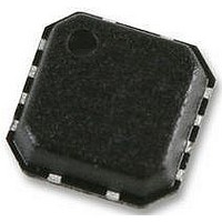
ADA4627-1ACPZ-R2 Analog Devices Inc, ADA4627-1ACPZ-R2 Datasheet - Page 13

ADA4627-1ACPZ-R2
Manufacturer Part Number
ADA4627-1ACPZ-R2
Description
IC OPAMP JFET 16MHZ LN 8LFCSP
Manufacturer
Analog Devices Inc
Datasheet
1.ADA4627-1ARZ.pdf
(16 pages)
Specifications of ADA4627-1ACPZ-R2
Slew Rate
84 V/µs
Design Resources
High Speed Instrumentation Amplifier Using AD8271 and ADA4627-1 (CN0122)
Amplifier Type
J-FET
Number Of Circuits
1
Gain Bandwidth Product
19MHz
Current - Input Bias
1pA
Voltage - Input Offset
120µV
Current - Supply
7mA
Current - Output / Channel
45mA
Voltage - Supply, Single/dual (±)
±5 V ~ 15 V
Operating Temperature
-40°C ~ 125°C
Mounting Type
Surface Mount
Package / Case
8-LFCSP
Op Amp Type
FET/JFET Input
No. Of Amplifiers
1
Bandwidth
19MHz
Supply Voltage Range
± 5V To ± 15V
Amplifier Case Style
LFCSP
No. Of Pins
8
Operating Temperature Range
-40°C
Lead Free Status / RoHS Status
Lead free / RoHS Compliant
Output Type
-
-3db Bandwidth
-
Lead Free Status / RoHS Status
Lead free / RoHS Compliant, Lead free / RoHS Compliant
Other names
ADA4627-1ACPZ-R2TR
oscillator is connected to the circuit under test, and the output
of the circuit goes back to the analyzer.
The analyzer has a tunable notch filter in lock step with the
swept oscillator. This removes the fundamental frequency,
but allows all of the harmonics and wideband noise to be
measured with an integrating voltmeter. However, there is
a switchable low-pass filter in series with the notch filter.
If the sine wave is at 100 Hz, then the tenth harmonic is still
at 1 kHz, thus having a low pass at 80 kHz is not a problem.
When the oscillator reaches 20 kHz, the fourth harmonic
(80 kHz) is partially attenuated, resulting in a lower reading
from the voltmeter. When evaluating THD + N curves from
any manufacturer, careful attention should be paid to the test
conditions. The difference between an 80 kHz low-pass filter
and a 500 kHz filter is shown in Figure 39.
PRINTED CIRCUIT BOARD LAYOUT, BIAS
CURRENT, AND BYPASSING
To take advantage of the very low input bias current of the
ADA4627-1 at room temperature, leakage paths must be
considered. A printed circuit board, with dust and humidity,
can have 100 MΩ of resistance over a few tenths of an inch.
A 1 mV differential between the two points results in 10 pA
of leakage current, more than the guaranteed maximum.
The op amp inputs should be guarded by surrounding the nets
with a metal trace maintained at the predicted voltage. In the
case of an inverting configuration or transimpedance amplifier,
(see Figure 40), the inverting and noninverting nodes can be
surrounded by traces held at a quiet analog ground.
0.00001
0.0001
0.001
0.01
0.01
I
N
ADA4627-1
T
V
V
R
Figure 40. Inverting Amplifier with Guard
A
GUARD
SY
IN
L
= 25°C
= 600Ω
= 810mV
= ±15V
Figure 39. THD + N vs. Frequency
0.1
500kHz FILTER
FREQUENCY (kHz)
2
3
ADA4627-1
1
8
C
R
80kHz FILTER
F
F
6
10
V
OUT
+
–
100
Rev. B | Page 13 of 16
For a noninverting configuration, the trace can be driven from
the feedback divider, but the resistors should be chosen to offer
a low impedance drive to the trace (see Figure 41).
The board layout should be compact with traces as short as
possible. For second-order board considerations, such as
triboelectric effects and piezoelectric effects, as well as a table
of insulating material properties, see the
In some cases, shielding from air currents may be helpful.
A general rule of thumb, for op amps with gain bandwidth
products higher than 1 MHz, bypass capacitors should be very
close to the part, within 3 millimeters. Each supply should be
bypassed with a 0.01 μF ceramic capacitor in parallel with a
1 μF bulk decoupling capacitor. The ceramic capacitors should
be closer to the op amp. Sockets, which add inductance and
capacitance, should not be used.
OUTPUT PHASE REVERSAL
Output phase reversal occurs in some amplifiers when the input
common-mode voltage range is exceeded. As common-mode
voltage is moved outside the common-mode range, the outputs
of these amplifiers can suddenly jump in the opposite direction
to the supply rail. This is the result of the differential input pair
shutting down, causing a radical shifting of internal voltages
that results in the erratic output behavior.
The ADA4627-1 amplifier has been carefully designed to
prevent any output phase reversal if both inputs are maintained
within the specified input voltage range. If one or both inputs
exceed the input voltage range but remain within the supply
rails, an internal loop opens and the output varies. Therefore,
the inputs should always be a minimum of 3 V away from either
supply rail.
DRIVING CAPACITIVE LOADS
Adding capacitance to the output of any op amp results in addi-
tional phase shift, which reduces stability and leads to overshoot
or oscillation. The ADA4627-1 has a high phase margin and low
output impedance, so it can drive reasonable values of capacitance.
This is a common situation when an amplifier is used to drive the
input of switched capacitor ADCs. For other considerations and
various circuit solutions, see the Analog Dialogue article titled
Ask the Applications Engineer-25, Op Amps Driving Capacitive
Loads, available at www.analog.com.
V
S
Figure 41. Noninverting Amplifier with Guard
+
–
GUARD
3
2
ADA4627-1
8
AD549
6
ADA4627-1
R
R
data sheet.
V
–
F
I
OUT
+


