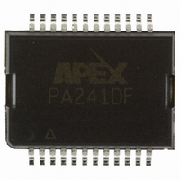
PA241DF Cirrus Logic Inc, PA241DF Datasheet - Page 6

PA241DF
Manufacturer Part Number
PA241DF
Description
OP AMP HV 350V .06A 24-PSOP DF
Manufacturer
Cirrus Logic Inc
Series
Apex Precision Power™r
Specifications of PA241DF
Amplifier Type
Power
Number Of Circuits
1
Slew Rate
30 V/µs
Gain Bandwidth Product
3MHz
Current - Input Bias
50pA
Voltage - Input Offset
25000µV
Current - Supply
2.2mA
Current - Output / Channel
120mA
Voltage - Supply, Single/dual (±)
100 V ~ 350 V, ±50 V ~ 175 V
Operating Temperature
-25°C ~ 85°C
Mounting Type
Surface Mount
Package / Case
24-PSOP
Number Of Channels
1
Voltage Gain Db
96 dB
Common Mode Rejection Ratio (min)
84 dB
Input Offset Voltage
40 mV
Maximum Operating Temperature
+ 85 C
Mounting Style
SMD/SMT
Maximum Dual Supply Voltage
+/- 175 V
Minimum Operating Temperature
- 25 C
For Use With
598-1459 - EVALUATION KIT FRO PA241DF
Lead Free Status / RoHS Status
Lead free / RoHS Compliant
Output Type
-
-3db Bandwidth
-
Lead Free Status / Rohs Status
Details
Other names
598-1357
Available stocks
Company
Part Number
Manufacturer
Quantity
Price
Part Number:
PA241DF
Manufacturer:
APEX
Quantity:
20 000
PA241
6
200
120
100
200
120
100
50
40
30
20
10
50
40
30
20
10
5
4
3
2
5
4
3
2
10
10
PULSE CURVES @ 10% DUTY CYCLE MAX
PULSE CURVES @ 10% DUTY CYCLE MAX
SUPPLY TO OUTPUT DIFFERENTIAL, V
SUPPLY TO OUTPUT DIFFERENTIAL, V
20
20
30
30
PA241CE and DF SOA
PA241DW SOA
50
50
100
100
200 300
200 300
S
S
-V
-V
O
O
(V)
(V)
500
500
P r o d u c t I n n o v a t i o n F r o m
FIGURE 1
OVERVOLTAGE PROTECTION
up to 16V, in some applications additional external protection
may be needed. Differential inputs exceeding 16V will be clipped
by the protection circuitry. However, if more than a few milliamps
of current is available from the overload source, the protection
circuitry could be destroyed. For differential sources above
16V, adding series resistance limiting input current to 1mA will
prevent damage. Alternatively, 1N4148 signal diodes connected
anti-parallel across the input pins is usually sufficient. In more
demanding applications where bias current is important, diode
connected JFETs such as 2N4416 will be required. See Q1
and Q2 in Figure 1. In either case the differential input voltage
will be clamped to 0.7V. This is sufficient overdrive to produce
the maximum power bandwidth.
the diodes mentioned above will also afford protection from
excessive common mode voltage. In the case of non-invert-
ing circuits, clamp diodes from each input to each supply will
provide protection. Note that these diodes will have substantial
reverse bias voltage under normal operation and diode leak-
age will produce errors.
devices connected to the power supply rails. Unidirectional
zener diode transient suppressors are recommended. The
zeners clamp transients to voltages within the power supply
rating and also clamp power supply reversals to ground.
Whether the zeners are used or not the system power supply
should be evaluated for transient performance including power-
on overshoot and power-off polarity reversals as well as line
regulation. See Z1 and Z2 in Figure 1.
APPLICATION REFERENCES:
lowing Application Notes:
AN1: General Operating Considerations
AN3: Bridge Circuit Drives
AN25: Driving Capacitive Loads
AN38: Loop Stability with Reactive Loads
Although the PA241 can withstand differential input voltages
In the case of inverting circuits where the +IN pin is grounded,
Some applications will also need over-voltage protection
For additional technical information please refer to the fol-
+IN
-IN
Q1
Q2
+Vs
-Vs
+Vs
-Vs
Z2
Z1
OUT
PA241U


