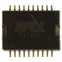
PA78DK Cirrus Logic Inc, PA78DK Datasheet - Page 4

PA78DK
Manufacturer Part Number
PA78DK
Description
IC PWR AMP 350V 200MA 20PSOP
Manufacturer
Cirrus Logic Inc
Series
Apex Precision Power™r
Specifications of PA78DK
Amplifier Type
Power
Number Of Circuits
1
Slew Rate
350 V/µs
Gain Bandwidth Product
1MHz
Current - Input Bias
8.5pA
Voltage - Input Offset
8000µV
Current - Supply
700µA
Current - Output / Channel
150mA
Voltage - Supply, Single/dual (±)
20 V ~ 350 V, ±10 V ~ 175 V
Operating Temperature
-40°C ~ 125°C
Mounting Type
Surface Mount
Package / Case
20-PSOP
Number Of Channels
1
Voltage Gain Db
120 dB
Common Mode Rejection Ratio (min)
90 dB
Input Offset Voltage
25 mV
Operating Supply Voltage
300 V
Maximum Operating Temperature
+ 125 C
Mounting Style
SMD/SMT
Maximum Dual Supply Voltage
+/- 175 V
Minimum Operating Temperature
- 40 C
For Use With
598-1398 - KIT EVALUATION PA78/PA79
Lead Free Status / RoHS Status
Lead free / RoHS Compliant
Output Type
-
-3db Bandwidth
-
Lead Free Status / Rohs Status
Details
Other names
598-1351
Available stocks
Company
Part Number
Manufacturer
Quantity
Price
Part Number:
PA78DK
Manufacturer:
APEX
Quantity:
20 000
Part Number:
PA78DK/AO
Manufacturer:
APEX
Quantity:
20 000
— The load impedance of the piezoelectric actuator is given
by the expression:
lent circuit shown in Figure 4 is employed. By doing this,
the equivalent circuit of the piezoelectric actuator, shown in
Figure 2, is split into two parts with each part comprising a
2nF capacitor and a 0.5 ohm resistor, while assuming a virtual
ground denoted by the dotted line and the ground symbol.
Since the real part of the impedance (1 Ohm) is negligible
compared with the total capacitive reactance of 1989 Ohms,
it can be neglected.
Figure 4. Equivalent Circuit - For computing the maximum power dissipation for the two PA78s in the bridge circuit.
Figure 5. Deflection Plates Amplifier Circuit – The fast operational amplifier, AD817, in cascade with the PA78, provide a gain of
approximately 100 so that the output voltage applied to the deflection plates can be programmed between 0 and 300 volts.
APEX MICROTECHNOLOGY CORPORATION • 5980 NORTH SHANNON ROAD • TuCSON, ARIZONA 85741 • uSA • APPLICATIONS HOTLINE: 1 (800) 546-2739
4
Computing the maximum dissipated power per module
To compute the maximum power per module the equiva-
ω
(1)
voltage will be one half the total potential applied to each
module:
which is 1989 divided by 2 each — or 994.5 ohms.
the phase difference between V & I in the load. In this case it
is quite simple because we have modeled our load as a pure
capacitor, so the phase angle Φ is 90 degrees. The formula
for determining the maximum power dissipated in the case
of a reactive load for a phase angle greater than 40° can be
found in reference 3.
In the equivalent circuit depicted in Figure 4, the applied
The circuit for each half will drive half the capacitive reactance
The key to determining power dissipation begins with knowing
(2)


